Novel water conservancy equipment

A water conservancy and equipment technology, applied in the field of new water conservancy equipment, can solve the problems of troublesome disassembly and assembly of the reel well rope, easy aging and fracture of the well rope, low degree of automation, etc. Effect

Inactive Publication Date: 2018-01-16
CIXI QICHENG MACHINERY TECH CO LTD
View PDF0 Cites 0 Cited by
  • Summary
  • Abstract
  • Description
  • Claims
  • Application Information

AI Technical Summary

Problems solved by technology

In order to draw water safely and conveniently, a potter's wheel will be set up next to the well, but the potter's wheel needs to be rolled by hand to retract the well rope, which has a low degree of automation, and the well rope is easily distributed unevenly when it is wrapped around the head of the potter's wheel, which affects normal use. The well rope is blown by the wind. The rain is easy to age and break, so it needs to be replaced in time. The disassembly and assembly of the traditional potter's wheel well rope is very troublesome and dangerous

Method used


Image

  • Novel water conservancy equipment
  • Novel water conservancy equipment
  • Novel water conservancy equipment

Examples


Embodiment Construction

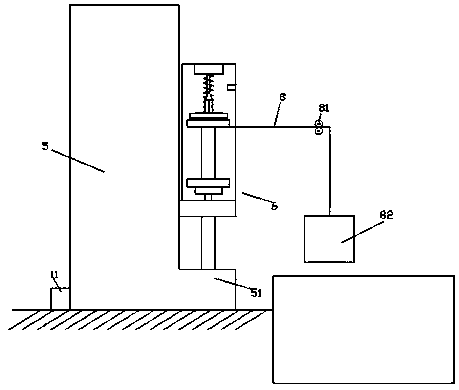
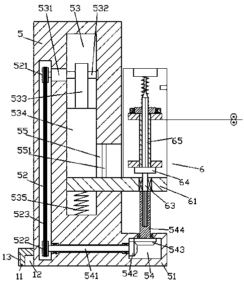
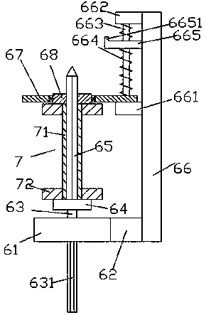
[0022] Such as Figure 1-Figure 6 As shown, a new type of water conservancy equipment of the present invention includes a column 5 fixedly installed on the edge of the well and a direction changing wheel 81 arranged on the right side of the column 5 and arranged up and down symmetrically. The right side of the column 5 A base 51 is provided at the bottom of the surface, and a rope receiving device 6 is arranged above the base 51, and the rope receiving device 6 includes a lifting plate 61 extended from left to right, a connecting block 62 fixed on the rear side of the lifting plate 61, The plate 66 fixed on the rear side of the connecting block 62 and extended upwards and the rope receiving seat 64 arranged above the lifting plate 61, the bottom of the rope receiving seat 64 is fixed with a first revolving shaft 63, so The bottom of the first revolving shaft 63 passes through the lifting plate 61 and is revolving and fitly connected. The bottom of the first revolving shaft 63 ...


PUM


Abstract

The invention discloses novel water conservancy equipment. The novel water conservancy equipment comprises a column fixedly installed on the edge of a water well and variable wheels arranged on the right side of the column in a up-and-down corresponding mode, a bottom platform is arranged on the bottom of the right side surface of the column, a rope collecting device is arranged over the bottom platform, the rope collecting device comprises a lifting board which extends in the leftward and rightward directions, a connecting block fixed to the rear side of the lifting board, a board which is fixed to the rear side of the connecting block and extends upward and a rope collecting base arranged over the lifting board, a first rotating shaft is fixedly arranged on the bottom of the rope collecting base, the bottom of the first rotating shaft penetrates the lifting board and is connected with the lifting board in a rotating and matched mode, an outer spline shaft which extends downward is fixedly arranged on the bottom of the first rotating shaft, a spiral rod is fixedly arranged on the top of the rope collecting base, a first conversion cavity is formed in the bottom platform, and an inner spline shaft which extends in the upward and downward directions is connected with the interior of the inner top of the first conversion cavity in a rotating and matched mode. The novel water conservancy equipment has the advantages that the structure is simple, vertical moving rope collecting work can be automatically controlled, the evenness of rope collecting is improved, fast dismounting and mounting of a rope shaft are achieved, and the stability of rope collecting is improved.

Description

technical field [0001] The invention relates to the field of water conservancy, in particular to a new type of water conservancy equipment. Background technique [0002] In areas with abundant groundwater, people will dig wells to extract groundwater for irrigation or living. In order to draw water safely and conveniently, a potter's wheel will be set up next to the well, but the potter's wheel needs to be rolled by hand to retract the well rope, which has a low degree of automation, and the well rope is easily distributed unevenly when it is wrapped around the head of the potter's wheel, which affects normal use. The well rope is blown by the wind. It is easy to age and break due to rain, so it needs to be replaced in time. The disassembly and assembly of the traditional pulley well rope is very troublesome and dangerous. Contents of the invention [0003] The technical problem to be solved by the present invention is to provide a new type of water conservancy equipment,...

Claims


Application Information

Patent Timeline
Patent Type & Authority Applications(China)
IPC IPC(8): E03B3/08
Inventor 郭丹枫何叶青
Owner CIXI QICHENG MACHINERY TECH CO LTD
Why Eureka
Try Eureka