
Industrial mechanical arm device

A mechanical arm and industrial technology, which is applied in the field of industrial mechanical arm devices, can solve the problems of low flexibility and insufficient power to meet the requirements, and achieve the effect of improving flexibility

Inactive Publication Date: 2018-01-16
CHENGDU HONGYUE TECH CO LTD
View PDF0 Cites 6 Cited by
  • Summary
  • Abstract
  • Description
  • Claims
  • Application Information

AI Technical Summary

Problems solved by technology

[0004] The purpose of the present invention is to provide an industrial mechanical arm device to solve the problems of the above-mentioned background technology that the flexibility is not high, the power cannot meet the requirements when working far away from the box, and only light work such as welding can be done.

Method used


Image

  • Industrial mechanical arm device
  • Industrial mechanical arm device

Examples


Embodiment Construction

[0014] The solution is clearly and completely described, and obviously, the described embodiments are only some embodiments of the present invention, rather than all embodiments. Based on the embodiments of the present invention, all other embodiments obtained by persons of ordinary skill in the art without making creative efforts belong to the protection scope of the present invention.

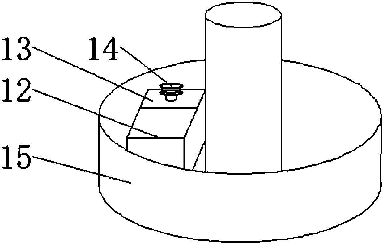
[0015] see Figure 1-2 , the present invention provides a technical solution: an industrial mechanical arm device, including a fixed pile 1, the periphery of the fixed pile 1 is provided with a sleeve cover 16, and the sleeve cover 16 is rotatably connected with the fixed pile 1, and the sleeve Cover 16 lower end is provided with box cover 9, and described box cover 9 lower end is provided with box body 15, and described box cover 9 and sleeve cover 16 are tightly welded, and described cover cover 16 right-hand side is provided with front and back symmetrical column 2, and the The column 2 i...


PUM


Abstract

The invention discloses an industrial mechanical arm device. The industrial mechanical arm device comprises a fixed pile, wherein a sleeve cover is arranged at the periphery of the fixed pile; a box cover is arranged at the lower end of the sleeve cover; a box body is arranged at the lower end of the box cover; the right end of the sleeve cover is provided with fore-and-aft symmetrical vertical columns; a hydraulic pump is arranged at the right end of the vertical column; a mechanical rear arm is arranged at the upper end between the vertical columns; a hydraulic pump is arranged at the rightend of the upper surface of the mechanical rear arm and is tightly welded with the mechanical rear arm; a mechanical front arm is arranged at the right end of the mechanical rear arm, and the mechanical rear arm is rotatably connected with the mechanical front arm; a rotator is arranged at the right end of the mechanical front arm; and a mechanical claw is arranged at the right end of the rotator.The industrial mechanical arm device disclosed by the invention has the advantages that the box cover can rotate by 360 degrees by adopting the fixed pile as an axle, the mechanical front arm and themechanical rear arm also can move under the power of the hydraulic pump, can work on a working platform surface farther from main power, and the power is much larger than that of the existing mechanical arm, the rotator can provide rotation, and the hydraulic pump at the right end also can provide pressure.

Description

technical field [0001] The invention relates to the technical field of mechanical arm devices, in particular to an industrial mechanical arm device. Background technique [0002] The development of the robotic arm was developed on the basis of the earliest ancient robots. The research on the robotic arm began in the middle of the 20th century. With the development of computers and automation technology, especially since the first digital electronic computer came out in 1946, computers have achieved At the same time, the urgent need for mass production promoted the development of automation technology, especially the development of robots laid the foundation. In this context, the United States developed a remote-controlled manipulator in 1974. Er first proposed the concept of industrial robots and applied for a patent. Using human hands to teach the robot's actions, the machine can realize actions and reproductions. The robotic arm generally has degrees of freedom. The higher...

Claims


Application Information

Patent Timeline
IPC IPC(8): B25J9/04B25J9/14B25J9/00
Inventor 冯扬
Owner CHENGDU HONGYUE TECH CO LTD
Learn More