Switch cabinet touch movable retaining plate locking device

A technology of movable baffles and locking devices, which is applied to switchgear, switchgear guards/protective devices, pull-out switch cabinets, etc., and can solve the problem of asynchronous movement on both sides of the movable baffle and easy jamming of the baffle connecting rod Stop trolleys, jamming of contact movable baffles and other problems, achieve high practical value and promotion value, convenient inspection and flexible action

Inactive Publication Date: 2018-01-12
UNIV FOR SCI & TECH SICHUAN
View PDF1 Cites 0 Cited by
  • Summary
  • Abstract
  • Description
  • Claims
  • Application Information

AI Technical Summary

Problems solved by technology

For example, the Chinese patent application No. 201220702151.8 discloses an electromagnetic locking device for the contact baffle of the electric switch cabinet with a central trolley. The movable door of the contact baffle is driven to open and close by the baffle link. The plate link method, its disadvantage is that the movable baffle of the contact is slid and supported by the metal rod penetrating through the side, and the movable baffle of the contact is lifted and lowered by the baffle link, and when the trolley is pulled out, the contact baffle In actual production, it often occurs that the two sides of the movable baffle move asynchronously, which causes the movable baffle of the contact to be stuck, and the connecting rod of the baffle is easy to jam the trolley, making the switch unable to advance and retreat. It needs to dismantle many switch parts to recover, which not only delays the time of power outage and transmission, but also causes great economic losses, and its maintenance is relatively large

Method used


Image

  • Switch cabinet touch movable retaining plate locking device
  • Switch cabinet touch movable retaining plate locking device
  • Switch cabinet touch movable retaining plate locking device

Examples


Embodiment

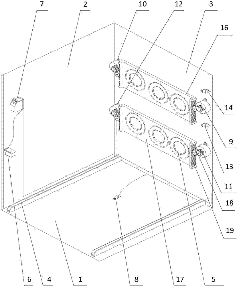
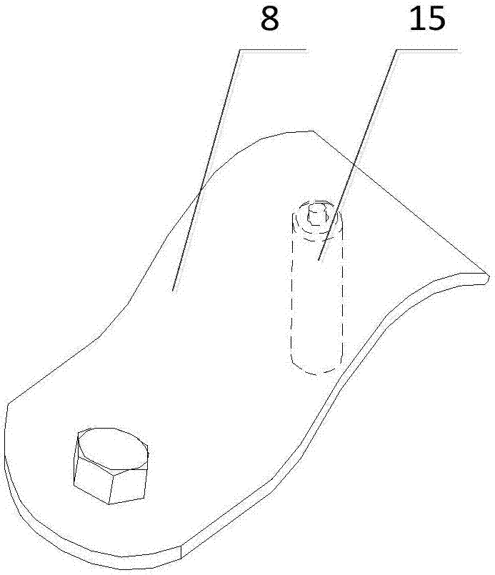
[0026] Such as Figure 1 to Figure 3 As shown, the present invention provides a kind of locking device for the movable baffle of the switchgear, the purpose is to make the operation of the movable baffle of the contact more safe and reliable, and it can be lifted flexibly. Movable baffle 16 and lower movable baffle 17, the electromagnetic lock 6 that is arranged on side wall 2, is arranged on the controller 7 on the side wall, the trolley position sensor 15 that is connected with controller 7, the first motor 9, the second The motor 10, the third motor 11, the fourth motor 12, the first stroke sensor 13 and the second stroke sensor 14, and the grounding shrapnel 8 which are arranged on the base plate 1 and are attached to the trolley position sensor 15, wherein the electromagnetic lock 6 and Controller 7 is connected.

[0027] The first motor and the second motor of the device are fixed on the partition and distributed on both sides of the upper movable baffle, and the third ...


PUM


Abstract

The invention discloses a switch cabinet touch movable retaining plate locking device and mainly solves the problem of jamming when existing touch movable retaining plates act in the prior art. The device comprises an upper movable retaining plate, a lower movable retaining plate, an electromagnetic lock arranged on a side wall, a controller arranged on the side wall, a handcart position sensor, afirst motor, a second motor, a third motor, a fourth motor, a first stroke sensor, a second stroke sensor and a grounded elastic piece arranged on the baseplate and fitted to the handcart position sensor, the upper movable retaining plate and the lower movable retaining plate are arranged on a partition, the handcart position sensor, the first motor, the second motor, the third motor, the fourthmotor, the first stroke sensor and the second stroke sensor are connected with the controller, and the electromagnetic lock is connected with the controller. Through the technical scheme, the switch cabinet touch movable retaining plate locking device has the advantages of simple structure, convenience in operation, flexibility in action, safety and reliability and quite high practical value and popularization value in the technical field of safety protection.

Description

technical field [0001] The invention relates to the technical field of safety protection, in particular to a locking device for a movable baffle of a switch cabinet contact. Background technique [0002] A switchgear is an electrical device that controls the opening and closing of electrical circuits of various devices. The switch cabinet includes a busbar room, a switch room, and a switch. The switch room is composed of a bottom plate, a side wall and a partition. The partition is used to separate the switch room and the bus room. According to the internal structure, it can be divided into withdrawable switch cabinet and fixed switch cabinet. Among them, the withdrawable switch cabinet can be divided into drawer switch and trolley switch. When the trolley-type switch is powered off for maintenance, it is necessary to pull the trolley out to the maintenance position. The contact of the switch forms an obvious breaking point with the contacts of the busbar and the outgoing l...

Claims


Application Information

Patent Timeline
IPC IPC(8): H02B11/167H02B11/24
Inventor 孙向东
Owner UNIV FOR SCI & TECH SICHUAN
Why Eureka
Try Eureka