Eureka AIR delivers breakthrough ideas for toughest innovation challenges, trusted by R&D personnel around the world.

Distribution box heat dissipation system

A heat dissipation system and distribution box technology, applied in substation/power distribution device casing, electrical components, substation/switch layout details, etc., can solve problems affecting the operation of electrical components in the distribution box, and achieve the effect of convenience

Active Publication Date: 2018-01-12
宁波博恩电气有限公司
View PDF5 Cites 8 Cited by
  • Summary
  • Abstract
  • Description
  • Claims
  • Application Information

AI Technical Summary

Problems solved by technology

However, some distribution boxes are installed in the field. When it rains, rainwater easily enters the distribution box from the shutters, affecting the operation of the electrical components in the distribution box.

Method used


Image

  • Distribution box heat dissipation system
  • Distribution box heat dissipation system
  • Distribution box heat dissipation system

Examples


Embodiment Construction

[0026] The present invention will be further described in detail through specific embodiments below.

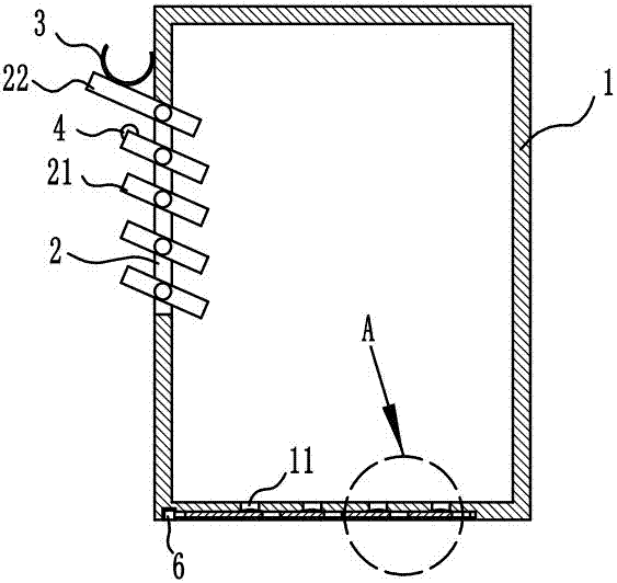
[0027] The reference signs in the accompanying drawings of the description include: box body 1, heat dissipation hole 2, water bag 3, photoresistor 4, mounting frame 5, telescopic cylinder 6, slider 7, rotating shaft 8, torsion spring 9, air vent 11, slider Groove 12, spacer 21, blocking plate 22, sealing plate 51, through hole 52.

[0028] Distribution box cooling system, such as figure 1 , figure 2 and image 3 As shown, a box body 1 is included, electrical components are installed in the box body 1, a heat dissipation hole 2 is opened on the box body 1, and a plurality of spacers 21 are arranged in the heat dissipation hole 2, and four spacers 21 are arranged in the present embodiment. Sheets 21 and spacers 21 are arranged in an inclined downward manner from the outside of the box body 1 toward the inside of the box body 1. The top of the cooling hole 2 is hinged with ...


PUM


Abstract

The invention relates to the technical field of electrical fittings, in particular to a distribution box heat dissipation system. A heat dissipation hole is formed in a box body, a plurality of partition pieces are arranged in the heat dissipation hole, the partition pieces all incline downwards and face the interior of the box body from the exterior of the box body, a baffle piece capable automatically restoring is hinged to the top of the heat dissipation hole, the gradient of the baffle piece is equal to those of the partition pieces, the width of the baffle piece is greater than those of the partition pieces, a water bag for collecting rainwater is arranged between the baffle piece and the box body, and the end of the partition piece adjacent to the baffle piece is provided with a photo-resistor which is arranged at the outer side of the box body; the distribution box heat dissipation system further includes a controller for receiving the resistance value of the photo-resistor, a plurality of ventilation holes are formed in a bottom plate of the box body, and seal pieces capable of being opened are arranged in the ventilation holes and are controlled by the controller to be opened according to the resistance value. According to the distribution box heat dissipation system, when it rains, the baffle piece shades the partition pieces below the baffle piece and shades the heatdissipation hole under the baffle piece from rain, the situation is avoided that rainwater enters the interior of the box body through the heat dissipation hole, and it is ensured that electrical elements in the box body run normally.

Description

technical field [0001] The invention relates to the technical field of electrical accessories, in particular to a cooling system for a distribution box. Background technique [0002] The distribution box has a wide range of applications, involving various aspects such as industry, agriculture, transportation and people's life. The distribution box is to assemble switchgear, measuring instruments, protective appliances and auxiliary equipment on metal cabinets or screens according to electrical wiring requirements. In order to distribute the electric energy reasonably, it is convenient to open and close the circuit. [0003] When the existing distribution box is working, the internal electrical components will emit heat, which will increase the temperature in the distribution box and affect the operation of the electrical components. Generally, the fan is used to fan the heat, and the fan will transfer the heat from the distribution box. The heat dissipation holes are conduc...

Claims


Application Information

Patent Timeline
IPC IPC(8): H02B1/46H02B1/28H02B1/56
Inventor 陈亮
Owner 宁波博恩电气有限公司
Why Eureka
Eureka Blog
Learn More