
A snap-in type communication cable

A communication cable and cable technology, which is applied in the direction of connection, installation of connection parts, and parts of connection devices, etc., can solve problems such as large use limitations, cumbersome connection and installation process, and space impact, so as to achieve signal connection and fast The effect of convenient insertion

Active Publication Date: 2018-12-04
ZHONGSHAN RUISU ELECTRONICS CO LTD
View PDF6 Cites 0 Cited by
  • Summary
  • Abstract
  • Description
  • Claims
  • Application Information

AI Technical Summary

Problems solved by technology

[0002] The signal connection mode between the existing audio-visual playback equipment and the display speaker equipment is mostly a snap-in adapter type, and one end of the incoming line needs to be connected with a separate line, that is, the two products can be connected. The transmission of line-of-sight signals will not only affect the space, but also the price is high, and the connection and installation process is relatively cumbersome; there is another type that uses screws to lock the wires to the panel, which hinders operability and versatility. Can not achieve fast plug-in connection, the use of large limitations

Method used


Image

  • A snap-in type communication cable
  • A snap-in type communication cable
  • A snap-in type communication cable

Examples


Embodiment Construction

[0017] The following will clearly and completely describe the technical solutions in the embodiments of the present invention with reference to the accompanying drawings in the embodiments of the present invention. Obviously, the described embodiments are only some, not all, embodiments of the present invention. Based on the embodiments of the present invention, all other embodiments obtained by persons of ordinary skill in the art without creative efforts fall within the protection scope of the present invention.

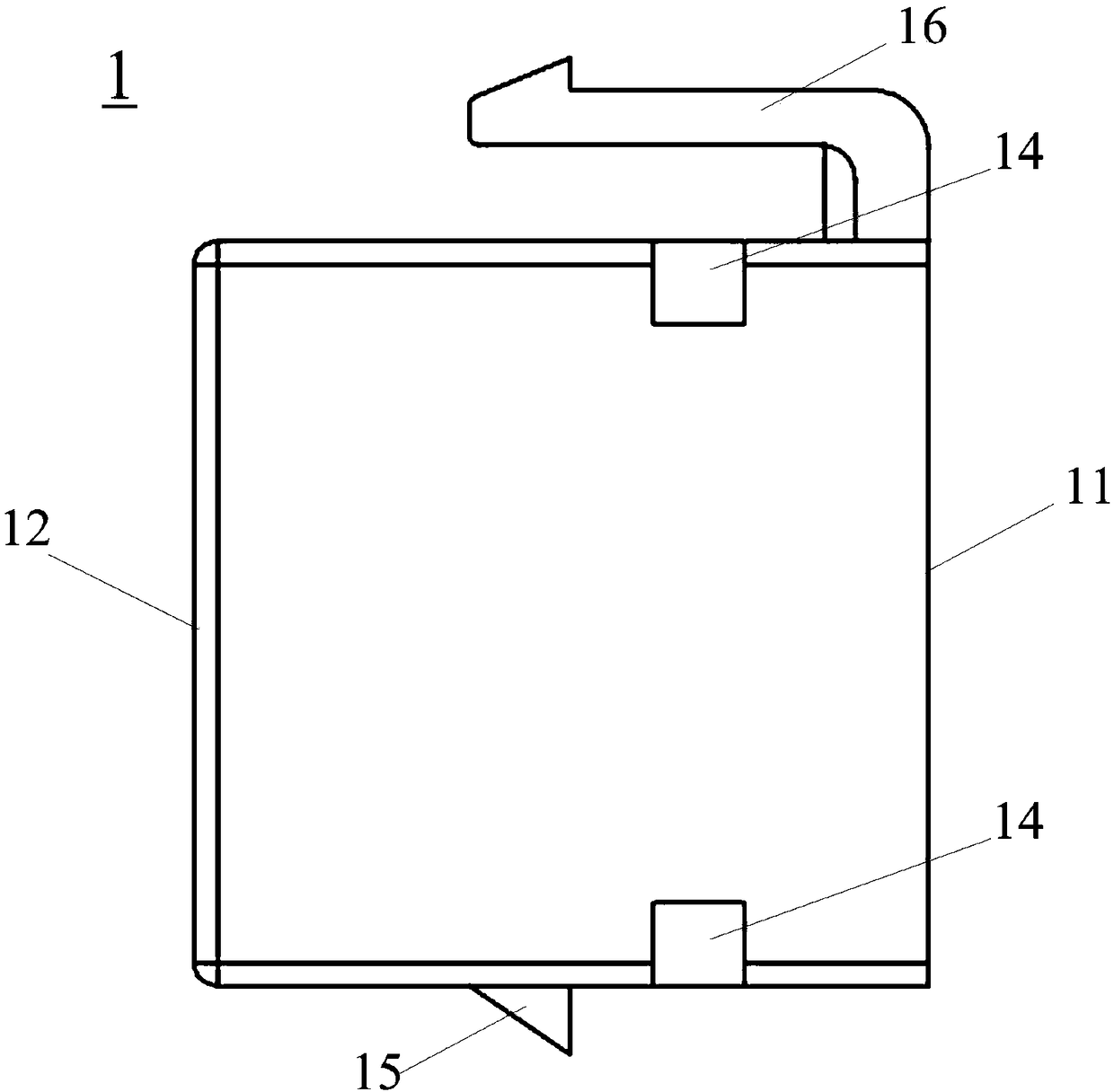
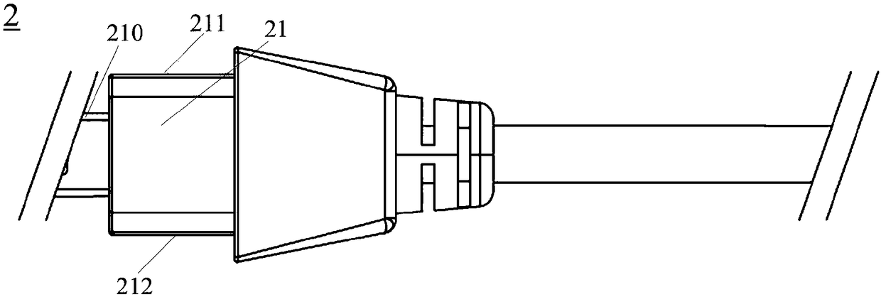
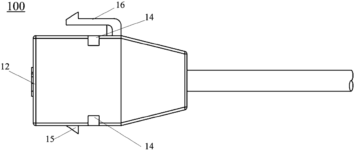
[0018] Such as Figure 1 to Figure 3 As shown, the embodiment of the present invention provides a snap-in communication cable 100 . The snap-in communication cable 100 includes a socket housing 1 and a molded cable body 2 . Wherein, the socket housing 1 is a hollow frame, and two opposite ends of the socket housing 1 are respectively provided with a first socket 11 and a second socket 12, and the first socket 11 and the second socket 12 are both It communicates w...


PUM


Abstract

The invention discloses a clamp connection type communication cable. The clamp connection type communication cable comprises a molding cable body and a socket casing, wherein two opposite ends of thesocket casing are respectively provided with a first plugging port and a second plugging port, the first plugging port and the second plugging port are communicated with an inner chamber of the socketcasing, a plug of the molding cable body can be completely accommodated in the chamber of the socket casing, a front end of the plug of the molding cable body forms an input / output interface, two opposite outer side walls of the plug of the molding cable body are provided with a first magnetic portion and a second magnetic portion which have opposite magnetism, two opposite inner side walls of the chamber of the socket casing are respectively provided with a third magnetic portion and a fourth magnetic portion which have opposite magnetism, when the plug of the molding cable body is plugged into the chamber of the socket casing through the first plugging port in the positive direction, the first magnetic portion and the third magnetic portion realize mutual attraction, the second magneticportion and the fourth magnetic portion realize mutual attraction, so the plug of the molding cable body is fixed in the chamber of the socket casing, and thereby the clamp connection type communication cable after assembling is formed.

Description

technical field [0001] The invention belongs to the field of electric connection, and in particular relates to a snap-in type communication cable. Background technique [0002] The signal connection mode between the existing audio-visual playback equipment and the display speaker equipment is mostly a snap-in adapter type, and one end of the incoming line needs to be connected with a separate line, that is, the two products can be connected. The transmission of line-of-sight signals will not only affect the space, but also the price is high, and the connection and installation process is relatively cumbersome; there is another type that uses screws to lock the wires to the panel, which hinders operability and versatility. Also can not realize fast plug-and-play connection, use limitation is bigger. Contents of the invention [0003] In view of the defects existing in the prior art, the purpose of the embodiments of the present invention is to provide a snap-in type commun...

Claims


Application Information

Patent Timeline
Patent Type & Authority Patents(China)
IPC IPC(8): H01R13/506H01R13/627H01R13/73
Inventor 高启奎
Owner ZHONGSHAN RUISU ELECTRONICS CO LTD
Learn More