Refrigerating system

A refrigeration system and condenser technology, applied in the field of refrigeration systems, can solve problems such as air-supply mixing loss, and achieve the effects of reducing mixing loss, improving heating performance, and improving energy efficiency levels

Pending Publication Date: 2018-01-12
GREE ELECTRIC APPLIANCES INC
View PDF1 Cites 9 Cited by
  • Summary
  • Abstract
  • Description
  • Claims
  • Application Information

AI Technical Summary

Problems solved by technology

[0005] Therefore, the technical problem to be solved by the present invention is to overcome defects such as the mixing loss of supplementary air in the refrigeration system in the prior art using two-stage or quasi-secondary supplementary air to increase enthalpy, thereby providing a refrigeration system

Method used


Image

  • Refrigerating system
  • Refrigerating system
  • Refrigerating system

Examples


Embodiment 1

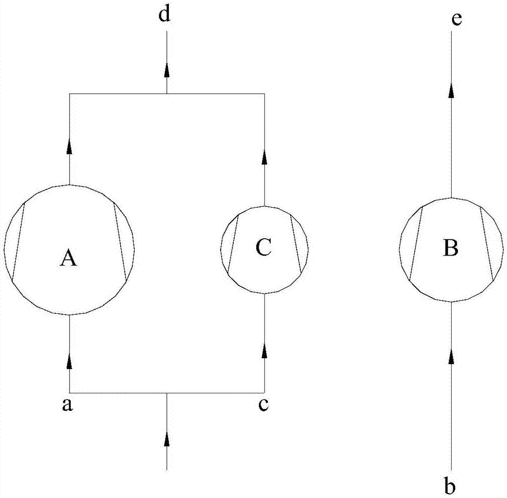
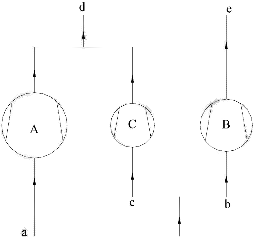
[0066] Such as figure 1 , Preferably, there is one switching compression chamber, which is the third compression chamber C, and there is also one gas supply port c, which is the first gas supply port c, and the suction end of the third compression chamber C is the third The suction end is connected to the first air supply port c, and the exhaust end of the third compression chamber C is the third exhaust port, which is connected to the first exhaust port d. This is the preferred number of parallel independent cylinders and switching compression chambers, the preferred number and connection mode of the air supply port of the refrigeration system embodiment 1 of the present invention, the switching compression chamber and the air supply port are all set as one, and the third compressor The suction end of the cavity is connected to the first air supply port, and the refrigerant (refrigerant from the first air supply branch of the refrigeration system) can be sucked in through the...

Embodiment 2

[0081] Such as Figure 5-7b , there are two switching compression chambers, the third compression chamber C and the fourth compression chamber D, the two gas supply ports are the first gas supply port c and the second gas supply port f, and the third compression The suction end of the chamber C is the third suction end, which is connected to the first gas supply port c, and the exhaust end of the third compression chamber C is the third exhaust end, which is connected to the first row The air port d is connected; the suction end of the fourth compression chamber D is the third suction end, which is connected to the second air supply port f, and the exhaust end of the fourth compression chamber D is the third exhaust end , which is connected to the second exhaust port e.

[0082] This is the preferred number of parallel independent cylinders and switching compression chambers, the preferred number and connection mode of the air supply ports of the refrigeration system embodime...


PUM


Abstract

The invention provides a refrigerating system. The refrigerating system comprises a compressor (1), an evaporation device and a condensation device; the compressor comprises more than two compressioncavities and further comprises more than one switching compression cavity, more than one air supplement port and more than one air supplement branch (10), wherein the compression cavities are independent from each other, and the air supplement branches (10) are located outside the compressor; the air supplement ports can be connected to at least one of the air supplement branches (10); the air suction ends of the switching compression cavities are connected to the air supplement ports; and the exhaust ends of the switching compression cavities are connected to an exhaust port of the compressor. Compared with an original two-stage or quasi-two-stage air supplement enthalpy increasing system loop, the refrigerating system has the beneficial effects that a technology combining air supplemententhalpy increasing and parallel compression is adopted, air supplement enthalpy increasing can be realized by utilizing the air supplement branches, the mixing loss of air supplement can be effectively reduced, the backflow loss and the flowing resistance loss of air supplement can be reduced, and therefore the air supplement enthalpy increasing effect can be improved, the heating capacity of therefrigerating system at a low temperature can be improved, and the energy efficiency level of the system can be improved.

Description

technical field [0001] The invention belongs to the technical field of air conditioning, and in particular relates to a refrigeration system. Background technique [0002] The patent with publication number CN105444453A proposes a dual-temperature refrigeration and heating system realized by a single-stage two-cylinder compressor. By using two cylinders and two connected four-way valves and corresponding different refrigerant circuits, Realize dual evaporating temperature cooling or dual condensing temperature heating, dual-temperature cooling or dual-temperature heating realize cascade cooling or heating, and improve the energy efficiency level of the system. [0003] However, the heating capacity of the dual-temperature system will rapidly decay as the outdoor ambient temperature drops. In order to solve this problem, two-stage or quasi-two-stage compression intermediate air supplementation technology is generally used to increase enthalpy, but there are various degrees of...

Claims


Application Information

Patent Timeline
IPC IPC(8): F25B13/00F25B31/00F25B41/00F25B41/06F25B41/04F04C18/356F04C29/12F25B41/20F25B41/31F25B41/40
Inventor 郑波方金升梁祥飞黄柏良庄嵘
Owner GREE ELECTRIC APPLIANCES INC
Why Eureka
Try Eureka