
Punching device used for building and working method thereof

A punching device and technology for construction, which is applied in the field of construction equipment, can solve problems such as difficult discharge of punching residue, overloaded operation of the device, and weak fixed connection, etc., to achieve unlimited punching conditions, reduce operating load, and punch holes The effect of consistent verticality of the inner cavity

Inactive Publication Date: 2018-01-12
陈彬
View PDF9 Cites 1 Cited by
  • Summary
  • Abstract
  • Description
  • Claims
  • Application Information

AI Technical Summary

Problems solved by technology

[0004] The object of the present invention is to provide a drilling device for construction and its working method, to solve the problems in the above background technology that the fixed connection is not firm enough to cause the device to fall off and damage the device during the drilling process, and the drilling residue is not easy to discharge, which leads to the occurrence of a hole in the drilling process. The device is overloaded, and the structural design is unreasonable, which leads to the limitation of hardness conditions when drilling holes in sand and gravel. The concentricity of the rotating running part leads to non-vertical drilling, and troublesome problems and deficiencies in replacement.

Method used


Image

  • Punching device used for building and working method thereof
  • Punching device used for building and working method thereof
  • Punching device used for building and working method thereof

Examples


Embodiment Construction

[0026] The technical solutions in the embodiments of the present invention will be clearly and completely described below in conjunction with the accompanying drawings in the embodiments of the present invention. Obviously, the described embodiments are only a part of the embodiments of the present invention, rather than all the embodiments. Based on the embodiments of the present invention, all other embodiments obtained by those of ordinary skill in the art without creative work shall fall within the protection scope of the present invention.

[0027] See Figure 1 to Figure 4 , The present invention provides a technical solution:

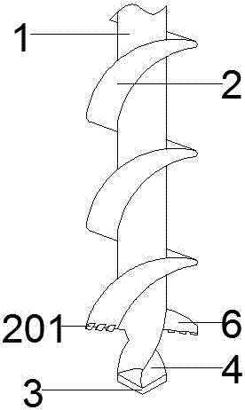
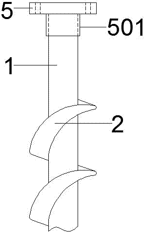
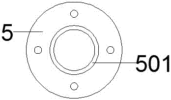
[0028] A drilling device for construction, comprising: a rod body 1, a blade 2, an alloy cutter head 3, a drill bit 4, a connector 5, a blade cutter head 201, and a sleeve 501; it is characterized in that the blade 2 is arranged on the periphery of the rod body 1, and And the blade 2 and the rod body 1 are connected by welding; the alloy bit 3 is set...


PUM


Abstract

The invention relates to the technical field of construction equipment, in particular to a punching device used for building and a working method thereof. The punching device comprises blades, an alloy cutting head and a drill bit. The punching device is characterized in that the blades are arranged on the periphery of a rod body and are connected with the rod body in a welded mode; the alloy cutting head is arranged in the drill bit and is connected with the drill bit in the welded mode; the drill bit is arranged at one end of the rod body, and the drill bit and the rod body are each of an integrated structure; blade cutting heads are arranged at one ends of the blades and are connected with the blades in the welded mode; and a sleeve and a connector are each of an integrated structure, and the sleeve and the rod body are connected in the welded mode. Through improvement of the structure, the punching device used for building has the advantages that connecting is firm, punching residues are easy to discharge, the operating load is reduced, the punching condition is not limited, positioning during punching is accurate, perpendicularity of punching cavities is the same, and the punching performance is high, and the problems existing in an existing device are effectively solved.

Description

Technical field [0001] The present invention relates to the technical field of construction equipment, in particular to a punching device for construction and a working method thereof. Background technique [0002] With the rapid development of modernization, the construction industry has become the leader in many industries, and the construction projects are diverse and diversified. Especially the requirements for punching during construction are extremely demanding, and building punching devices have emerged. [0003] However, the currently used punching device has a weak fixed connection, which causes the device to fall off and damage the device during the punching process. The punching residue is not easy to discharge, which causes the device to overload during the punching process. The unreasonable structure design causes the sand and gravel conditions to suffer when punching. Limited by the hardness conditions, the concentric rotation of the running part leads to problems and...

Claims


Application Information

Patent Timeline
IPC IPC(8): E21B7/04E21B10/44E21B10/42
Inventor 陈彬
Owner 陈彬
Learn More