
Precise lifting control device and drilling device

A lifting control and precise technology, applied in lifting devices, drilling/drilling equipment, manufacturing tools, etc., can solve problems such as construction safety and drilling errors, and achieve the effect of improving construction accuracy

Pending Publication Date: 2018-01-12
CCCC FOURTH HIGHWAY ENG
View PDF0 Cites 6 Cited by
  • Summary
  • Abstract
  • Description
  • Claims
  • Application Information

AI Technical Summary

Problems solved by technology

[0005] The purpose of the present invention is to provide a precise lifting control device and a drilling device to solve technical problems such as construction safety and drilling errors in the prior art during anchor construction after planting bars

Method used


Image

  • Precise lifting control device and drilling device
  • Precise lifting control device and drilling device
  • Precise lifting control device and drilling device

Examples


specific Embodiment

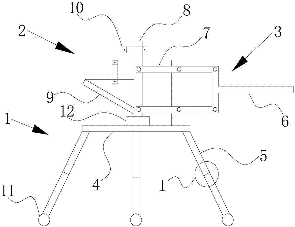
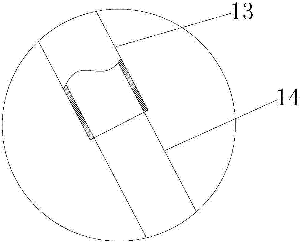
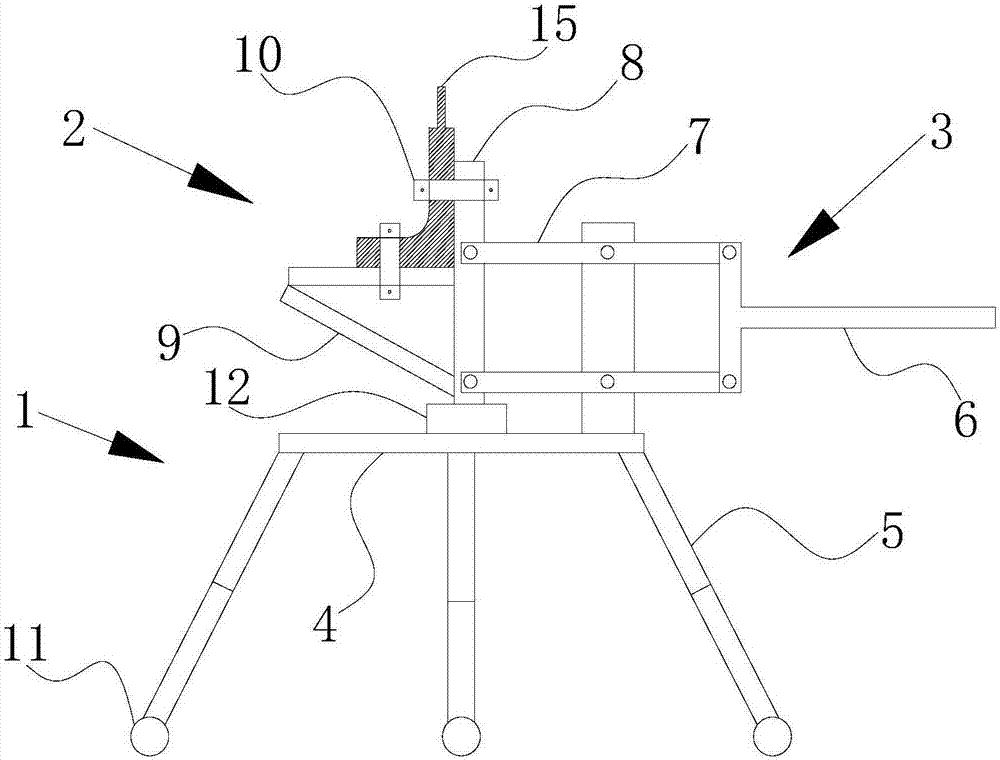
[0039] This embodiment provides a precise lifting control device, wherein: figure 1 Schematic diagram of the structure of the precise lifting control device provided by the embodiment of the present invention. Such as figure 1 As shown, the precision lifting control device includes a base frame 1, a lifting seat 2, and a swing arm 3. Specifically, the base frame 1 includes a base platform 4 and a plurality of outriggers 5 supporting the base platform 4 , and the plurality of outriggers 5 are telescopic. The lifting base 2 is arranged on the base platform 4 by winding the swing arm 3 , and the lifting base 2 can translate up and down relative to the base platform 4 by rotating around the swing arm 3 . During construction, the base platform 4 and the lifting seat 2 are adjusted respectively, so that the precise lifting and positioning of the lifting seat 2 can be realized.

[0040] On the basis of the foregoing embodiments, further, as figure 1 As shown, one end of the swing...


PUM


Abstract

The invention provides a precise lifting control device, and relates to the technical field of engineering construction equipment. The precise lifting control device comprises a base frame, a liftingseat and a swinging moment arm; the base frame comprises a base platform and a plurality of supporting legs for supporting the base platform, and the multiple supporting legs are telescopic; the lifting seat is arranged on the base platform through the swinging moment arm; and when the swinging moment arm rotates, the lifting seat can horizontally move up and down relative to the base platform. According to the precise lifting control device, the base platform and the multiple supporting legs are arranged on the base frame, the base platform can ascend and descend through the multiple telescopic supporting legs, and the lifting seat can horizontally move up and down relative to the base platform, and therefore precise lifting positioning of the lifting seat can be realized by adjusting thebase platform and the lifting seat. On the basis, the invention further provides a drilling device.

Description

technical field [0001] The invention relates to the technical field of engineering construction equipment, in particular to a precise lifting control device and a drilling device. Background technique [0002] In the construction of modern engineering, the anchoring technology after planting bars has been widely used for its advantages of high construction safety, good reliability and simple construction equipment, especially in building reinforcement and reconstruction projects. It has been proved by engineering practice that this technology is a construction method with novel concept and advanced technology in the field of engineering construction. [0003] During the construction process of the post-planting anchor technology of building structures, it is often necessary to drill holes in reinforced concrete structures. When carrying out drilling construction at the bottom of the beam, the construction personnel need to hold an electric drill, stand on the ladder, and wo...

Claims


Application Information

Patent Timeline
IPC IPC(8): B23B45/14B66F11/00
Inventor 李胜旺赵飞
Owner CCCC FOURTH HIGHWAY ENG
Learn More