Braking device for motor driven mechanism
A brake device and motor technology, applied in the direction of brake types, deceleration device parts, mechanical equipment, etc., can solve the problems of large energy loss of electrical brakes, easy aging, and long service life of springs, so as to achieve small energy loss and prevent The effect of heating and strengthening the immobilization effect
- Summary
- Abstract
- Description
- Claims
- Application Information
AI Technical Summary
Problems solved by technology
Method used
Image
Examples
Embodiment Construction
[0025] In order to make the technical means, creative features, goals and effects achieved by the present invention easy to understand, the present invention will be further described below in conjunction with specific embodiments.
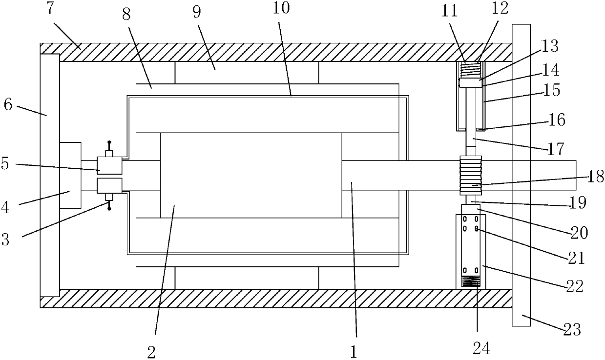
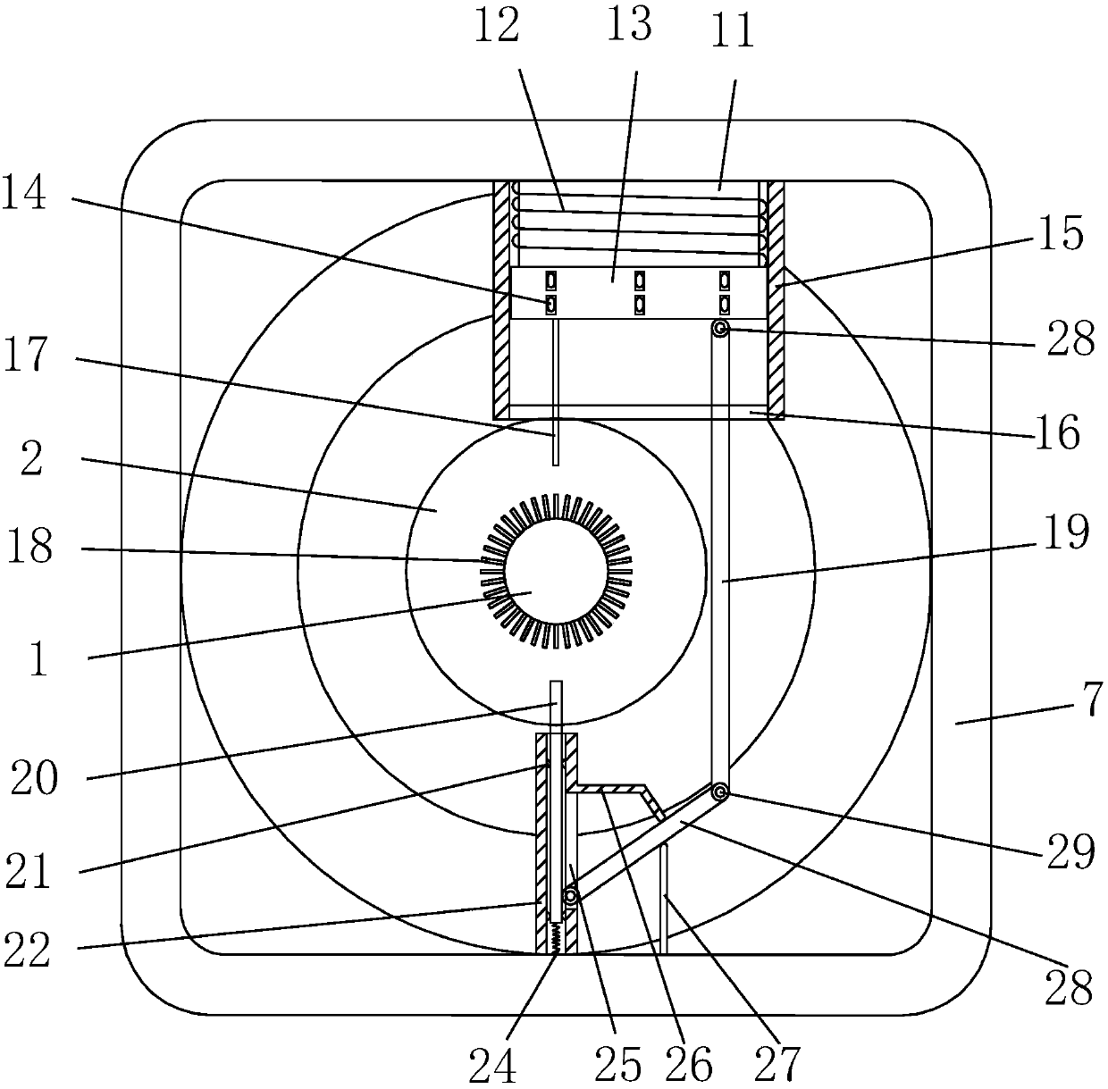
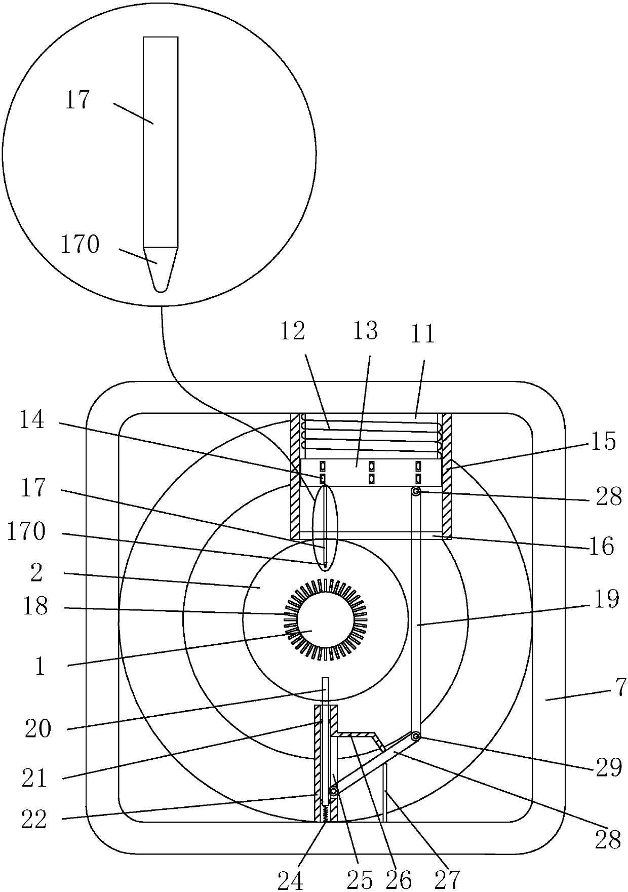
[0026] see Figure 1-Figure 6, the present invention provides a technical scheme of a brake device for a motor-driven mechanism: its structure includes a rotating shaft 1, a rotor core 2, a brush 3, a bearing 4, a commutator segment 5, a rear end cover 6, a housing 7, and a stator winding 8. Stator core 9, winding coil 10, core 11, coil 12, armature 13, roller I14, upper guide rail 15, limit block 16, upper brake pad 17, blade 18, connecting rod I19, lower brake pad 20, Roller II 21, lower guide rail 22, front end cover 23, spring 24, slot 25, baffle plate 26, vertical plate 27, connecting rod II 28, hinge 29, the rear end of the housing 7 is embedded with the rear end cover 6, the The front end cover 23 is arranged on the front end of the housin...
PUM
 Abstract
Description
Claims
Application Information
 - R&D Engineer
- R&D Manager
- IP Professional
- Industry Leading Data Capabilities
- Powerful AI technology
- Patent DNA Extraction
Browse by: Latest US Patents, China's latest patents, Technical Efficacy Thesaurus, Application Domain, Technology Topic, Popular Technical Reports.
© 2024 PatSnap. All rights reserved.Legal|Privacy policy|Modern Slavery Act Transparency Statement|Sitemap|About US| Contact US: help@patsnap.com


