


Quick Research
Generate reliable direction feasibility study reports for your R&D in just a few steps.

Technical Q&A
Discover and master advanced knowledge NOW. Basics, ideas, possibilities, all at once.

Find Solutions
As an expert in R&D theories, this can generate solutions to your technical problems instantly.

Evaluate Feasibility
Analyze your overall solution with one click, know your potential R&D risks in advance.

Monitor Landscape
Get weekly tech updates, stay abreast of the latest tech innovations and key insights.
Self-obstacle-crossing power transmission line deicing device
A transmission line, self-crossing technology, applied in the installation of cables, electrical components, overhead installation, etc., can solve the problems of danger, reduced spring deformation, inability to automatically climb over, etc., and achieves low labor input and high efficiency. Effect
- Summary
- Abstract
- Description
- Claims
- Application Information
AI Technical Summary
Problems solved by technology
Method used
Image

Examples
Embodiment 1
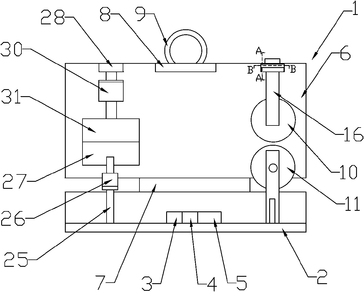
[0035] Such as figure 1 As shown, the deicing device for the self-obstacle-over power transmission line includes a frame body 1, and a deicing mechanism and a walking mechanism arranged in the frame body 1; the frame body 1 includes a bottom plate 2 and a One end is a vertical plate driven by a power mechanism to realize length adjustment, and the bottom plate 2 is provided with a power supply mechanism 3, a control mechanism 4 connected to the power supply mechanism 3, and a signal transmitting and receiving mechanism 5 connected to the control mechanism 4, The control mechanism 4 adopts a single-chip microcomputer, and the signal transmitting and receiving mechanism 5 adopts a GPRS module; the riser includes a first riser 6 and a second riser 7 set in the first riser 6, and the first riser The riser 6 and the second riser 7 are both hollow structures, and the first riser 6 is provided with a motor, a drive screw connected to the output end of the motor, a drive nut matched w...
Embodiment 2
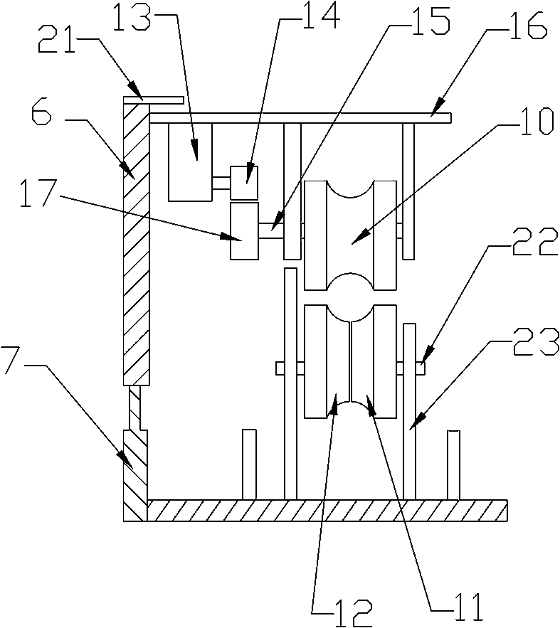
[0042] Such as figure 1 and Figure 7 As shown, this embodiment is basically the same as Embodiment 1, the difference is that the pressing wheel I11 and the pressing wheel II12 are driven by the power mechanism to walk along the length direction of the wire, and the pressing wheel I11 and the pressing wheel II12 The power mechanism adopts the servo motor II42, and the active helical gear 40 is driven by the servo motor II42. The pressing wheel I11 and the pressing wheel II12 are arranged on the vertical support 23 through the rotating shaft II22, and one end of the rotating shaft II22 is connected with the The driven helical gear 41 matched with the driving helical gear 40, the servo motor II42 is fixed on the vertical bracket 23 and connected with the control mechanism 4.
[0043] The pressing wheel I11 and pressing wheel II12 are driven by the power mechanism to walk along the wire, and cooperate with the traveling wheel 10 to jointly promote the walking of the deicing devi...
Embodiment 3
[0045] Such as figure 1 and Figure 8 As shown, the present embodiment is basically the same as the second embodiment, the difference is that an L-shaped connecting rod 43 is arranged on the outer wall of the first riser 6, and the direction of the interphase spacer bar on the double-split conductor is determined according to the The orientation of the connecting rod 43 is that if the interphase spacer is located on the lower side of the conductor, the connecting rod 43 faces upward, otherwise, the connecting rod 43 faces downward. According to the deicing requirements of the double-split wires, a crossbar driven by a power mechanism to adjust the length is connected between the two connecting rods 43, and the crossbar includes a first crossbar 44 and a first crossbar 44 sleeved in the first crossbar 44 Two crossbars 45, the first crossbar 44 and the second crossbar 45 are hollow structures, and the first crossbar 44 is provided with a motor, a transmission screw connected to...
PUM
 Abstract
Description
Claims
Application Information
 - R&D Engineer
- R&D Manager
- IP Professional
- Industry Leading Data Capabilities
- Powerful AI technology
- Patent DNA Extraction
Browse by: Latest US Patents, China's latest patents, Technical Efficacy Thesaurus, Application Domain, Technology Topic, Popular Technical Reports.
© 2024 PatSnap. All rights reserved.Legal|Privacy policy|Modern Slavery Act Transparency Statement|Sitemap|About US| Contact US: help@patsnap.com