


Quick Research
Generate reliable direction feasibility study reports for your R&D in just a few steps.

Technical Q&A
Discover and master advanced knowledge NOW. Basics, ideas, possibilities, all at once.

Find Solutions
As an expert in R&D theories, this can generate solutions to your technical problems instantly.

Evaluate Feasibility
Analyze your overall solution with one click, know your potential R&D risks in advance.

Monitor Landscape
Get weekly tech updates, stay abreast of the latest tech innovations and key insights.
A method of using a high-voltage transmission line deicing device
A technology for high-voltage transmission lines and transmission lines, which is applied in the installation of cables, overhead lines/cable equipment, overhead installation, etc., and can solve problems such as inconvenience in use
- Summary
- Abstract
- Description
- Claims
- Application Information
AI Technical Summary
Problems solved by technology
Method used
Image

Examples
Embodiment 1
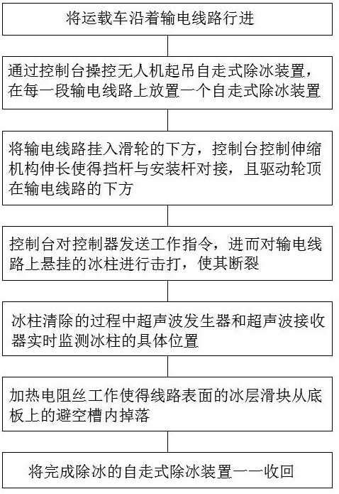
[0042] Such as figure 1 As shown, a method for using a high-voltage transmission line deicing device includes the following steps:
[0043] S1. Drive the carrier along the transmission line, and place a self-propelled deicing device on each section of the transmission line;
[0044] S2. The UAV is used to lift the self-propelled de-icing device through the console, and the telescopic mechanism on the bottom plate of the self-propelled de-icing device is in a retracted state;
[0045] S3. Hang the power transmission line under the pulley, and the console controls the extension of the telescopic mechanism so that the stop rod is connected to the installation rod, and the driving wheel is placed under the power transmission line;
[0046] S4. The console sends work instructions to the controller, and the controller controls the second driving mechanism to drive the slider so that the top rod squeezes the compression spring, and the compression spring collects energy and then eje...
Embodiment 2
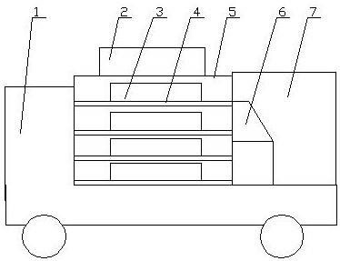
[0051] Such as figure 2 As shown, the present invention provides a high-voltage transmission line deicing device, including a carrier vehicle 1, a compartment 5 arranged at the rear of the carrier vehicle 1, a shelf 4 arranged in the compartment 5, and a shelf 4 arranged on the shelf Several self-propelled deicing devices 3 in 4, a control room 7 arranged at the rear of the compartment 5, a console 6 arranged in the control room 7, and an unmanned aerial vehicle arranged at the top of the compartment 5 2, and a fixing mechanism arranged on the lower part of the drone 2 and corresponding to the self-propelled deicing device 3; the console 6 is signal-connected with the drone 2 and the self-propelled deicing device 3, The self-propelled deicing device 3 includes a traveling mechanism on which a deicing mechanism is arranged.
[0052] The high-voltage transmission line deicing device includes a carrier vehicle, a carriage is arranged at the rear of the carrier, shelves are arra...
Embodiment 3
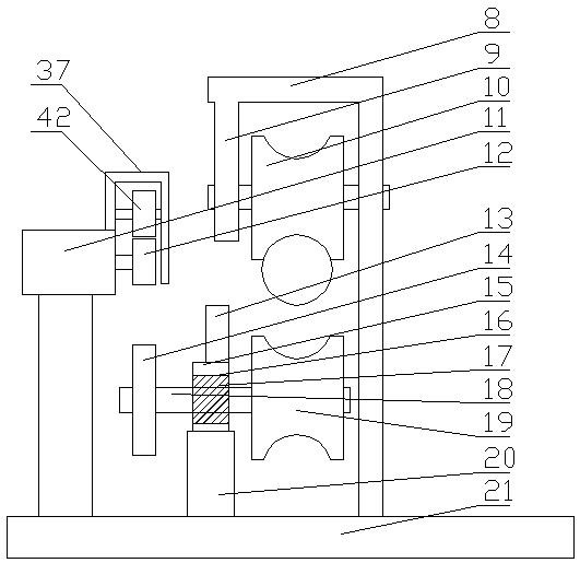
[0054] Such as image 3 and Figure 4 As shown, the difference between this embodiment and embodiment two is:
[0055] Described walking mechanism comprises base plate 21, and the top of described base plate 21 two ends is provided with L-shaped support 8, and the top of described L-shaped support 8 is provided with mounting rod 9 downwards, and described mounting rod 9 and described L-shaped support 8 are provided with Pulley 10, telescoping mechanism 20 is set on described base plate 21 below described installation bar 9, and the upper end of described telescoping mechanism 20 is provided with installation block 15, and vertical stop bar 13 is set on described installation block 15, and described installation A mounting hole 16 is arranged in the middle of the block 15, and a rotating shaft 18 parallel to the central axis of the pulley 10 is set through a bearing 17 in the mounting hole 16, and a driving wheel 19 matched with the pulley 10 is arranged on the rotating shaft ...
PUM
 Abstract
Description
Claims
Application Information
 - R&D Engineer
- R&D Manager
- IP Professional
- Industry Leading Data Capabilities
- Powerful AI technology
- Patent DNA Extraction
Browse by: Latest US Patents, China's latest patents, Technical Efficacy Thesaurus, Application Domain, Technology Topic, Popular Technical Reports.
© 2024 PatSnap. All rights reserved.Legal|Privacy policy|Modern Slavery Act Transparency Statement|Sitemap|About US| Contact US: help@patsnap.com