Piezoelectric vibration sounding module
A sounding module and piezoelectric vibration technology, applied in the direction of sounding devices, piezoelectric/electrostrictive transducers, electrical components, etc., to achieve a wide range of applications, reduce device costs, and save volume
- Summary
- Abstract
- Description
- Claims
- Application Information
AI Technical Summary
Problems solved by technology
Method used
Image

Examples
Embodiment 1
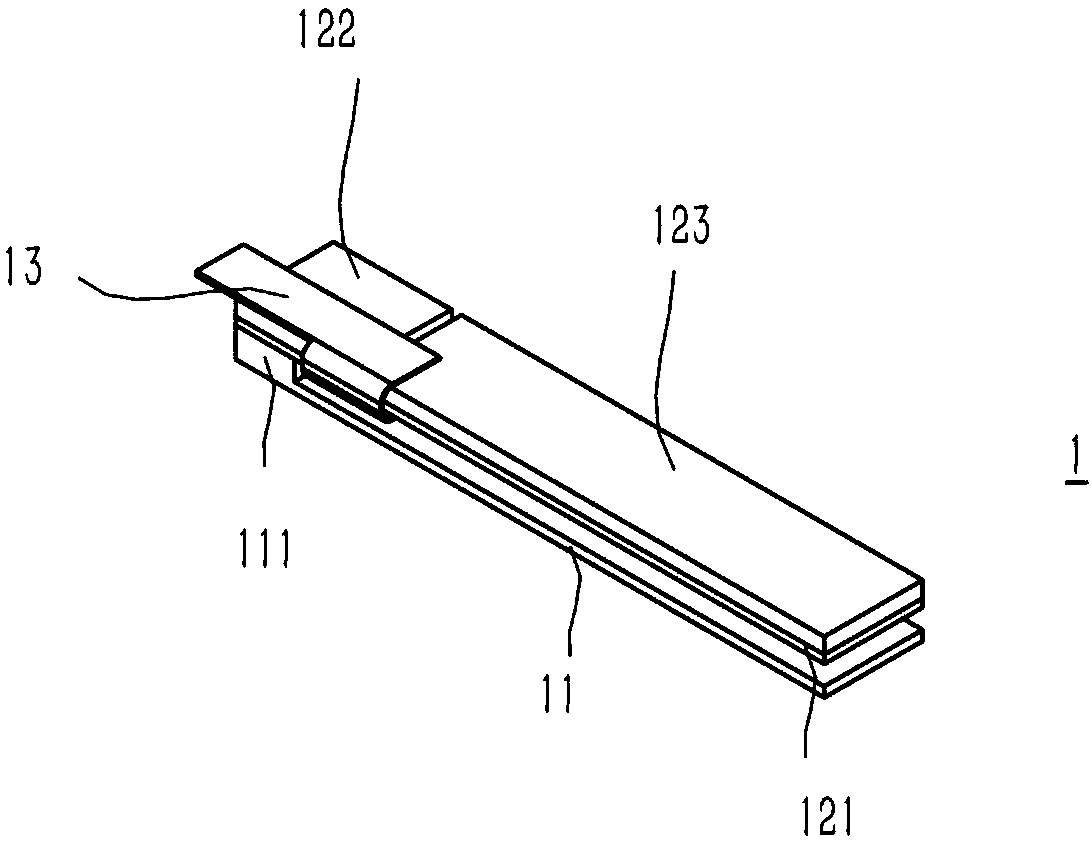
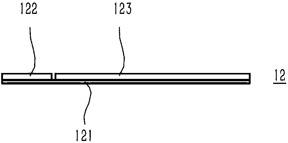
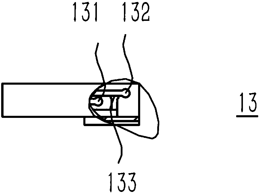
[0034] A piezoelectric vibration-sounding module, the vibration-sounding module 1 includes a base 111 and a cantilever beam 12, the cantilever beam 12 is arranged on the base 111, the cantilever beam 12 is provided with at least one fixed area and fixed on the base 111 through the fixed area, the cantilever beam The fixed area on 12 is a fixed end, and the remaining free parts are free ends. The vibration and sound module 1 also includes a hardened piezoelectric sheet 122 for changing the resonance frequency of the vibration and sound module 1 and a vibrating piezoelectric sheet 123 for providing vibration. Both the piezoelectric sheet 122 and the vibrating piezoelectric sheet 123 are provided with at least one, the hardened piezoelectric sheet 122 is arranged at the fixed end of the cantilever beam 12 and extends from the initial end of the fixed end to the free end, and the vibrating piezoelectric sheet 123 is arranged at the free end of the cantilever beam 12 And extending f...
Embodiment 2
[0043] Such as Figure 4 and 5 As shown, the difference between this embodiment and Embodiment 1 is that one cantilever beam 12 is provided, the middle part of the cantilever beam 12 is a fixed area, and the two ends of the cantilever beam 12 fixed area are two free ends of the cantilever beam 12; One is located in the middle of the base 111; a hardened piezoelectric sheet 122 is arranged and fixed in a fixed area in the middle of the cantilever beam 12, the hardened piezoelectric sheet 122 covers the fixed area and its two ends extend to the two free ends of the cantilever beam 12 respectively, and the hardened piezoelectric sheet 122 The edges of both ends of the sheet 122 exceed the edge of the boss 112; two vibrating piezoelectric sheets 123 are arranged on two free ends of the cantilever beam 12. The fixed area in the middle extends, and there is a distance between the two vibrating piezoelectric sheets 123 and the hardened piezoelectric sheet 122 . At the same time, th...
Embodiment 3
[0045] Such as Figure 6 and 7 As shown, the difference between this embodiment and Embodiment 1 is that one cantilever beam 12 is provided, and a fixed area is provided at both ends of the cantilever beam 12, thereby forming two fixed ends, and the area between the two fixed ends is the cantilever arm 12 free ends; boss 112 is provided with two and is respectively positioned at the two ends of base 111, and the fixed end of cantilever beam 12 two ends is respectively fixed on two bosses 112; Cantilever beam 12 two ends are respectively provided with a hardened piezoelectric sheet 122, the hardened piezoelectric sheet 122 is arranged on the fixed end of the cantilever beam 12 and extends to the free end, the length of the hardened piezoelectric sheet 122 is greater than the length of the corresponding boss 112, and a vibrating piezoelectric sheet 123 is arranged in the middle of the cantilever beam 12, and the vibration pressure The electric sheet 123 extends from the middle ...
PUM
 Abstract
Description
Claims
Application Information
 - R&D
- Intellectual Property
- Life Sciences
- Materials
- Tech Scout
- Unparalleled Data Quality
- Higher Quality Content
- 60% Fewer Hallucinations
Browse by: Latest US Patents, China's latest patents, Technical Efficacy Thesaurus, Application Domain, Technology Topic, Popular Technical Reports.
© 2025 PatSnap. All rights reserved.Legal|Privacy policy|Modern Slavery Act Transparency Statement|Sitemap|About US| Contact US: help@patsnap.com