
Uniformity debugging method and device, equipment and computer readable storage medium

A debugging method and uniformity technology, applied in the direction of calculation, digital output to display devices, instruments, etc., can solve the problems of the uniformity debugging scheme unable to realize automatic debugging, complicated operation, inconvenient operation, etc., so as to reduce the amount of calculation and simplify the calculation. , the effect of optimizing efficiency

Active Publication Date: 2018-01-09
BOE TECH GRP CO LTD
View PDF6 Cites 0 Cited by
  • Summary
  • Abstract
  • Description
  • Claims
  • Application Information

AI Technical Summary

Problems solved by technology

[0004] The uniformity debugging scheme of the traditional splicing display device cannot realize automatic debugging, and manual debugging is required. Due to the large number of splicing pieces and light-emitting components in the splicing display device, the operation is very cumbersome, and with the increase of product size, more inconvenient to operate

Method used


Image

  • Uniformity debugging method and device, equipment and computer readable storage medium
  • Uniformity debugging method and device, equipment and computer readable storage medium
  • Uniformity debugging method and device, equipment and computer readable storage medium

Examples


Embodiment Construction

[0035] The application will be further described in detail below with reference to the drawings and embodiments. It can be understood that the specific embodiments described here are only used to explain the related invention, but not to limit the invention. In addition, it should be noted that, for ease of description, only the parts related to the invention are shown in the drawings.

[0036] It should be noted that the embodiments in the application and the features in the embodiments can be combined with each other if there is no conflict. Hereinafter, the present application will be described in detail with reference to the drawings and in conjunction with embodiments.

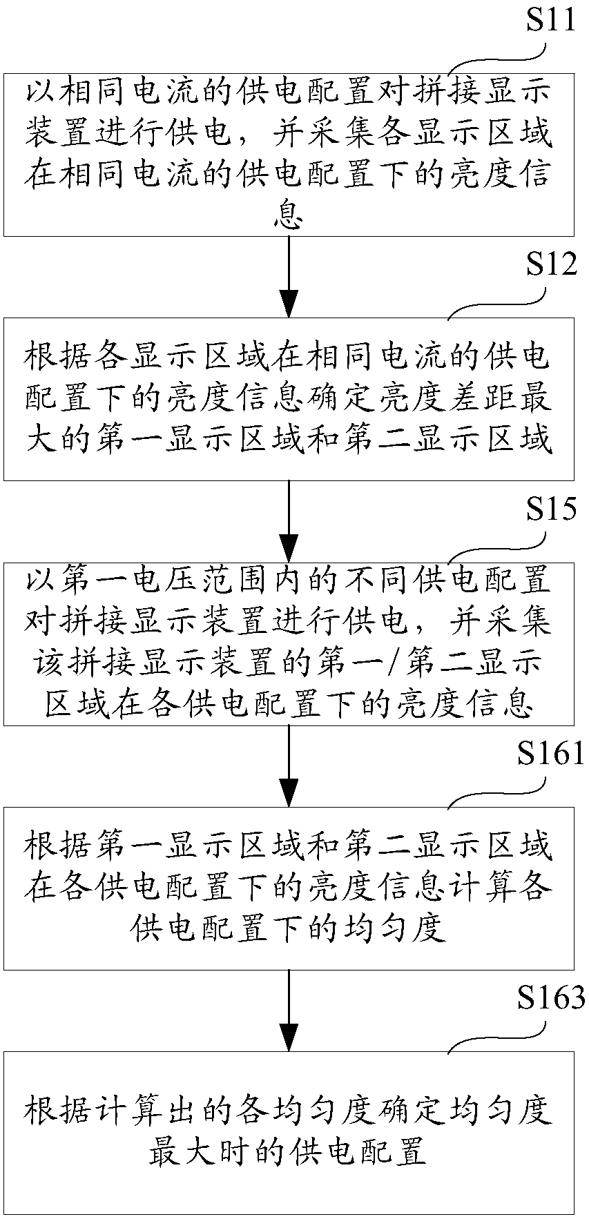
[0037] figure 1 It is a flowchart of a method for uniformity debugging provided by an embodiment of the present invention.

[0038] Such as figure 1 As shown, in this embodiment, a method for adjusting uniformity provided by the present invention includes:

[0039] S15: Power the spliced ​​display device with d...


PUM


Abstract

The invention provides a uniformity debugging method and device, equipment and a computer readable storage medium. The method comprises the steps of supplying power to a splicing display device with different kinds of power supply configuration in a first voltage range and acquiring brightness information of display areas of all splicing parts of the splicing display device under all power supplyconfiguration; calculating the uniformities of the splicing display device under all the power supply configuration according to all the brightness information and determining the power supply configuration when the uniformity is the largest. By automatically traversing the different kinds of power supply configuration which meet brightness requirements, the corresponding brightness information isobtained, according to all the brightness information, all the uniformities are calculated, the power supply configuration corresponding to the largest uniformity is finally determined, and automaticdebugging of the uniformities of the splicing display device is achieved.

Description

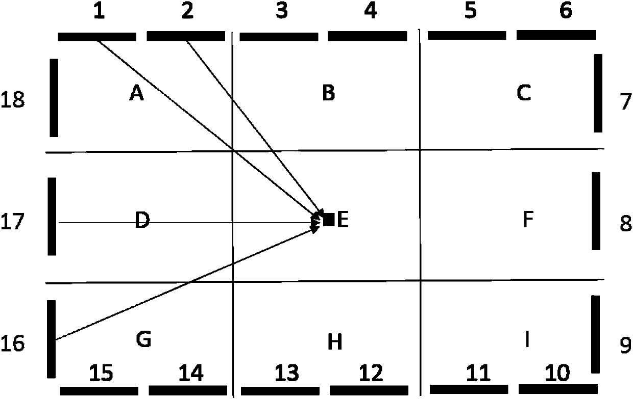
Technical field [0001] This application relates to the technical field of display device debugging, in particular to a uniformity debugging method and device, equipment, and computer-readable storage medium. Background technique [0002] With the rapid development of social informatization, large-size splicing display devices bring users an immersive visual experience with their unique large-scene display effects, and are welcomed by the market. [0003] However, as the size of the spliced ​​display device increases, the unequal brightness of the display areas that are spliced ​​with each other causes the problem that the overall brightness is not uniform, which affects the visual effect. For this problem, it is necessary to maximize the uniformity of the spliced ​​display device, so as to present the best visual effect. [0004] The uniformity debugging solution of the traditional splicing display device cannot realize automatic debugging, and manual debugging is required. Due to t...

Claims


Application Information

Patent Timeline
IPC IPC(8): G06F3/14
CPCG06F3/1446G09G3/2096G09G3/32G09G2300/026G09G2320/0233G09G2330/02G09G2300/0842
Inventor 杨凡冯朋朋王鑫
Owner BOE TECH GRP CO LTD
Learn More