


Quick Research
Generate reliable direction feasibility study reports for your R&D in just a few steps.

Technical Q&A
Discover and master advanced knowledge NOW. Basics, ideas, possibilities, all at once.

Find Solutions
As an expert in R&D theories, this can generate solutions to your technical problems instantly.

Evaluate Feasibility
Analyze your overall solution with one click, know your potential R&D risks in advance.

Monitor Landscape
Get weekly tech updates, stay abreast of the latest tech innovations and key insights.
Rapid soil loosening fertilizer applier of plant root zone
A fertilizer applicator and root zone technology, which is applied to agricultural machinery and implements, shovels, plows, etc., can solve the problem that the root loosening operation workload is too large and cannot be automatically fertilized in the root zone, etc. The effect of high work efficiency
- Summary
- Abstract
- Description
- Claims
- Application Information
AI Technical Summary
Problems solved by technology
Method used
Image

Examples
Embodiment 1
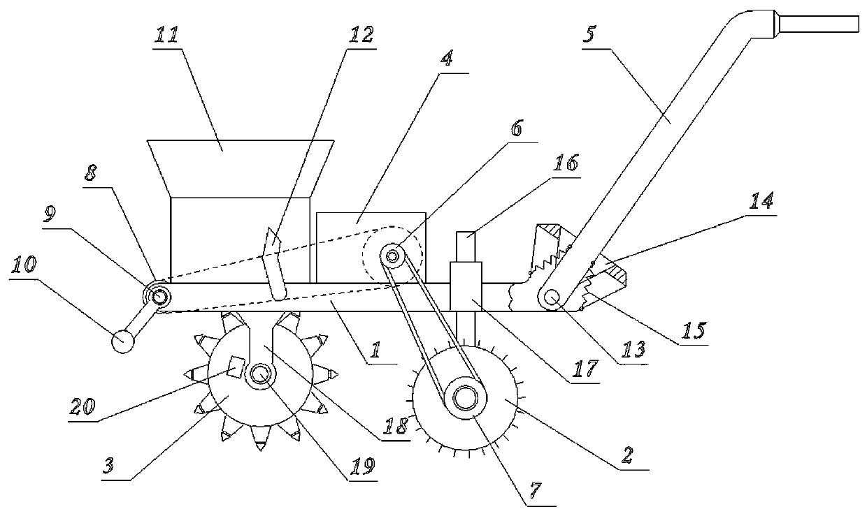
[0018] Embodiment 1: as figure 1 The shown plant root zone fast soil loosening fertilizer applicator comprises frame and drive mechanism 4 etc. Wherein, at least one fertilization wheel device 3 is set at the front side of the frame bottom, and a pair of road wheels 2 are installed at the rear side of the frame bottom, so that the frame is in a stable state.
[0019] The drive mechanism 4 positioned on the frame is connected with the road wheels 2 through a transmission mechanism. Driving mechanism 4 can adopt electric motor to wear accumulator, also can adopt fuel engine. The driving pulley 6 installed on the drive mechanism 4 output shafts is connected with the driven pulley-7 transmission on the belt and the road wheel 2 rotating shafts.
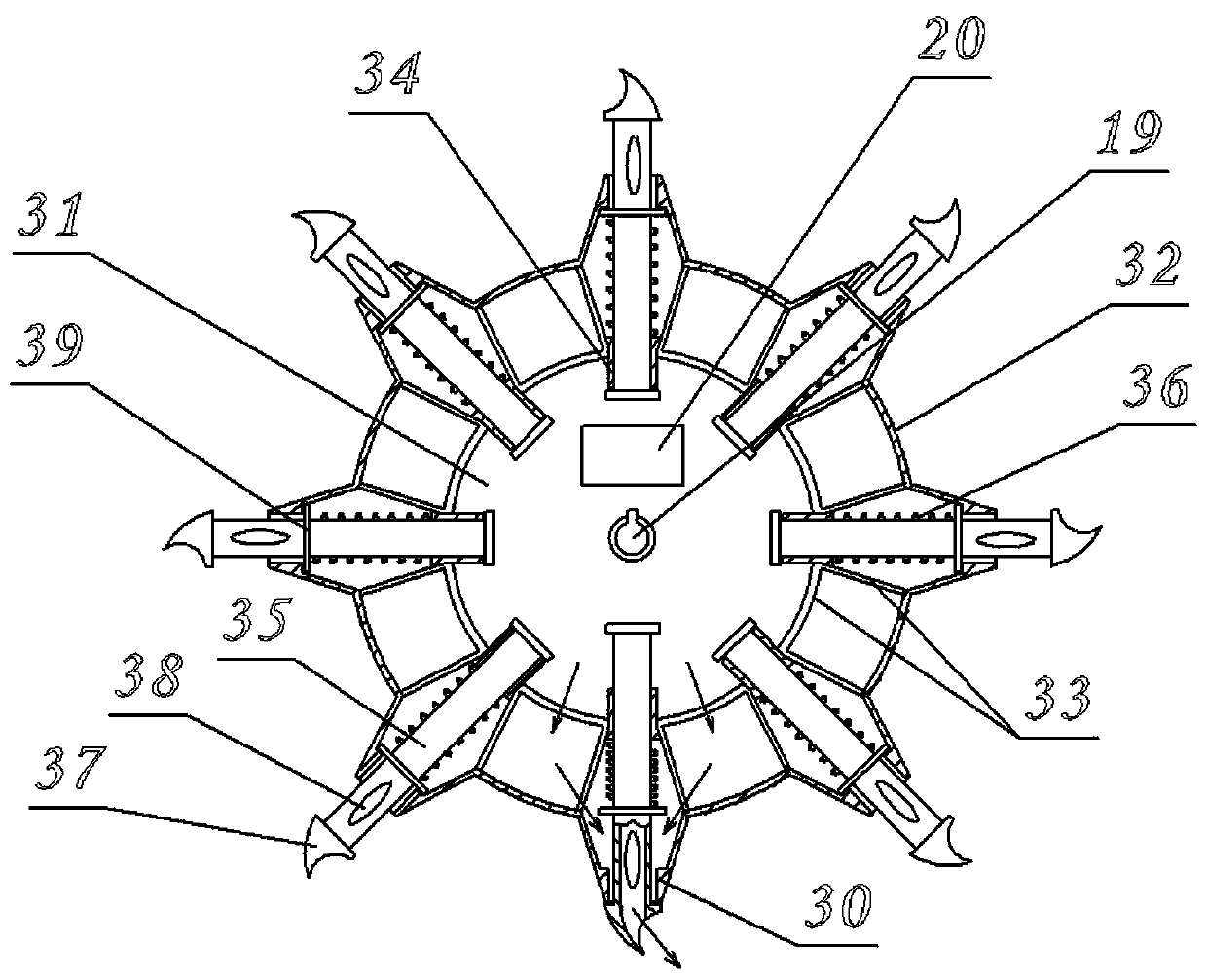
[0020] see figure 2 As shown, the fertilization wheel device 3 includes a disk shaft 19 installed on the bottom support of the vehicle frame 1 , and a disk body mounted on the disk shaft 19 . A feeding port and a cover 20 are arrange...
Embodiment 2
[0024] Embodiment 2: On the basis of Embodiment 1, an auxiliary driving mechanism is provided on the frame. see figure 1 A horizontal auxiliary shaft 9 is installed on the vehicle frame 1, and the auxiliary shaft 9 is transmission-connected with the driving mechanism 4, and a counterweight 10 is fixed at the end of the auxiliary shaft 9 through a connecting rod. At this moment, there are grousting teeth distributed on the periphery of the road wheel 2 again. The driven pulley one 7, the driving pulley 6 and the driven pulley two 8 of the road wheel 2 rotate synchronously, and since the ground teeth are set on the edge of the walking wheel, it is ensured that the whole machine is not slipping during the walking process, thereby ensuring the frequency stability. Utilizing the swing action of the counterweight body at an appropriate frequency, each driving tooth 30 can be forced to drive downward at the same frequency as the counterweight body, thereby further improving the dri...
PUM
 Abstract
Description
Claims
Application Information
 - R&D Engineer
- R&D Manager
- IP Professional
- Industry Leading Data Capabilities
- Powerful AI technology
- Patent DNA Extraction
Browse by: Latest US Patents, China's latest patents, Technical Efficacy Thesaurus, Application Domain, Technology Topic, Popular Technical Reports.
© 2024 PatSnap. All rights reserved.Legal|Privacy policy|Modern Slavery Act Transparency Statement|Sitemap|About US| Contact US: help@patsnap.com