
Cable bridge

A technology for cable trays and side panels, applied in electrical components and other directions, can solve problems such as wasted space and inability to adjust widths

Inactive Publication Date: 2018-01-05
江苏瑞仁汽车部件有限公司
View PDF3 Cites 1 Cited by
  • Summary
  • Abstract
  • Description
  • Claims
  • Application Information

AI Technical Summary

Problems solved by technology

The cable tray is a new type of cable laying device. The cable tray was originally used when laying cables. It is called a cable tray. Now it is not only used for laying cables, but also for laying and installing optical cables and pipes. Cable trays, most of the current cable trays are fixed, and the width cannot be adjusted, and when the cables need to be separated, two sets of trays need to be used in parallel, resulting in a waste of space

Method used


Image

  • Cable bridge

Examples


Embodiment Construction

[0017] In order to further explain the technical means and functions adopted by the present invention to achieve the intended invention purpose, the specific implementation, features and functions of the cable tray proposed according to the present invention are described in detail below.

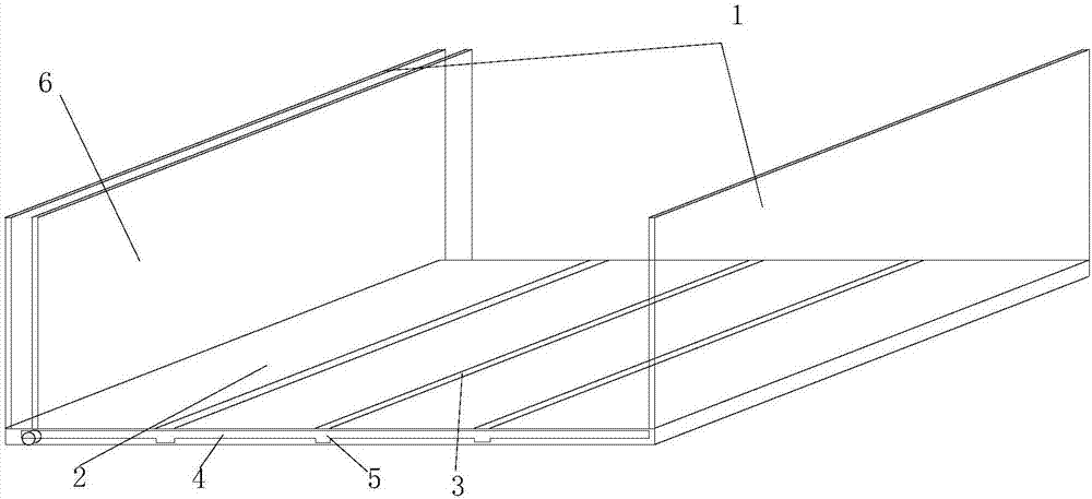
[0018] like figure 1 As shown, the present invention discloses a cable tray, including two side plates 1 and a bottom plate 2, the bottom plate 2 is provided with a first groove 3 parallel to the extending direction of the side plate 1 and a moving groove 4 perpendicular to the side plate 1 , wherein the part where the moving groove 4 is connected with the first groove 3 is provided with a second groove 5 .

[0019] It also includes a moving side plate 6, the two ends of the bottom of the moving side plate 6 have protruding legs, the moving side plate 6 can move along the moving groove 4 and has a first state and a tight seat in the first groove 3. The second state of the side panel 1. Sp...


PUM


Abstract

The invention discloses a cable bridge which comprises two side plates and a base plate. The cable bridge is characterized in that a first groove parallel to the extending direction of the side platesand a movable groove perpendicular to the side plates are formed in the base plate, wherein a second groove is formed in the portion, connected with the first groove, of the movable groove, the cablebridge further comprises a movable side plate, the two ends of the bottom of the movable side plate are provided with protruding supporting legs, and the movable side plate can move along the movablegroove and has the first state in which the movable side plate is clamped to the first groove and the second state in which the movable side plate abuts against the side plates; the movable side plate can slide along the movable groove and can be clamped to the second groove to be fixed, so that the cable bridge is divided into two independent spaces, width adjustment can be achieved, the interior can be divided into two independent spaces, and different cables can be placed in a separated mode.

Description

technical field [0001] The invention relates to the technical field of electric equipment, in particular to a cable tray. Background technique [0002] Composed of brackets, brackets, and installation accessories, it is a general term for rigid structures that independently support or fix cables to buildings (structures) and their attachments. The cable tray is a new type of cable laying device. The cable tray was originally used when laying cables. It is called a cable tray. Now it is not only used for laying cables, but also for laying and installing optical cables and pipes. Cable trays, most of the current cable trays are fixed, and the width cannot be adjusted, and when the cables need to be separated, two sets of trays need to be paralleled, resulting in a waste of space. [0003] In view of the defects of the above-mentioned existing cable trays, the inventor actively researches and innovates based on years of rich practical experience and professional knowledge in t...

Claims


Application Information

Patent Timeline
IPC IPC(8): H02G3/04
Inventor 梅仁平
Owner 江苏瑞仁汽车部件有限公司
Learn More