
Card taking device

A technology of card remover and card holder, which is applied in the direction of instruments, ticketing equipment, and ticket holders can manually access, etc., which can solve the problems of inconvenience, insecurity, and difficulty in reaching cards, etc., and achieves convenient use, flexible installation, and overall structure Set reasonable effects

Pending Publication Date: 2018-01-05
宜兴市培源实验小学
View PDF0 Cites 0 Cited by
  • Summary
  • Abstract
  • Description
  • Claims
  • Application Information

AI Technical Summary

Benefits of technology

This new technology allows for securely removing cards from windows while ensuring their security by allowing them to move along different distances within an enclosed space called the box or chamber where they were being used during testing sessions on electronic devices like smartphones.

Problems solved by technology

The technical problem addressed in this patented solution relates to making sure drivers get their cards inside when they enter certain locations such as gate-crossings or high ways without having them tethered up by safety harnesses that can be dangerous if left behind.

Method used


Image

  • Card taking device

Examples


Embodiment Construction

[0009] The present invention will be further described below in conjunction with drawings and embodiments.

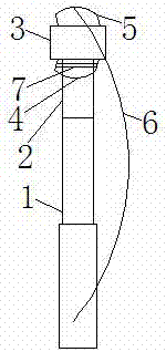
[0010] Such as figure 1 As shown, the card remover of the present invention includes a telescopic rod 1, a mounting plate 2 is provided at the front end of the telescopic rod 1, and a card removing clip is provided on the mounting plate 2, and the card removing clip includes The clip body 3 is symmetrically provided with two force application rings, respectively force application ring I4 and force application ring II5, and a force application belt 6 is provided on the force application ring II5, and the force application ring I4 passes through the clip holder 7 is fixedly connected with the installation plate 2; the clip holder 7 is a clip fixing rod or a clip fixing paper clip; the clip holder 7 passes through the connection hole provided on the installation board 2 to fix the force ring I4 on the installation plate 2. The overall structure of the present invention i...


PUM


Abstract

The invention relates to a card remover, which includes a telescopic rod, a mounting plate is arranged at the front end of the telescopic rod, and a card removing clip is arranged on the mounting plate, and the card removing clip includes a clip body, and the Two force application rings are arranged symmetrically on the body of the clip, respectively force application ring I and force application ring II. A force application belt is provided on the force application ring II, and the force application ring I is fixedly connected to the mounting plate through the clip holder. The invention can be telescopically adjusted, and is convenient and safe to use.

Description


Claims


Application Information

Patent Timeline
Owner 宜兴市培源实验小学
Learn More