Bladeless fan

A bladeless fan and blower technology, applied in multiple motor speed/torque control, electrical components, liquid fuel engines, etc., can solve the problems that cannot meet the control requirements of bladeless fans, increase the reliability requirements of bladeless fan systems, etc. , to achieve the effect of simple and reliable structural circuit, reduce circuit requirements, and simplify the circuit

Inactive Publication Date: 2018-01-05
程凌军
View PDF13 Cites 5 Cited by
  • Summary
  • Abstract
  • Description
  • Claims
  • Application Information

AI Technical Summary

Problems solved by technology

[0002] Bladeless fans are more and more accepted by people due to the relative safety brought by their lack of blades, and it is precisely because they do not have blades that they have a large gap with traditional fans in the selection of motors. And there are big differences in the process of controlling wind direction conversion and man-machine operation. For example, traditional fans only need to shake their heads to change the wind direction, so there is a control on the fan head. Mechanical switch, but because the motor of the bladeless fan is inside, mainly changing the position of the air duct to change the wind direction, so the traditional control system will not meet the control needs of the bladeless fan
[0003] In addition, with the continuous development of control technology, the technological requirements for human-computer interaction are getting higher and higher, so bladeless fans generally have corresponding operation interfaces or display interfaces for users to operate, which greatly improves the experience, but this This increases the reliability requirements for the bladeless fan system

Method used


Image

  • Bladeless fan
  • Bladeless fan
  • Bladeless fan

Examples


Embodiment

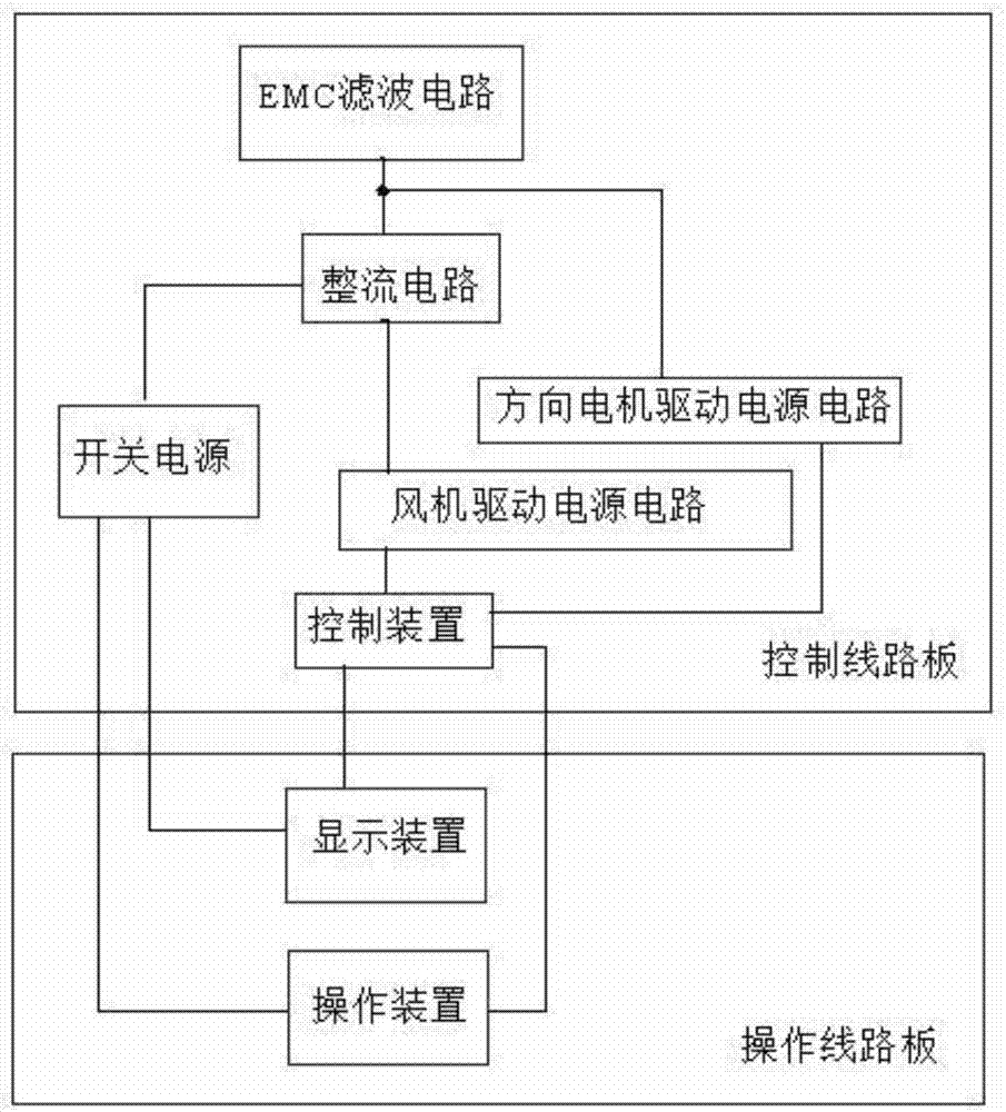
[0025] Such as figure 1 , as shown in 2, the bladeless fan includes at least one fan used to drive the wind flow, and a direction motor to change the wind direction, the fan is a brushless DC motor, and the direction motor is a claw pole permanent magnet synchronous motor, the brushless DC motor is driven by a fan drive power circuit, and the claw pole permanent magnet synchronous motor is driven by a directional motor drive power circuit.

[0026] In this embodiment, the bladeless fan further includes a control device, the control device controls the drive power supply circuit of the fan to work, so that the fan drives the corresponding impeller to work, so that the fan generates a corresponding air flow, the specific impeller The structure will not be described in detail here. At the same time, the control device also controls the direction motor to drive the power supply circuit to work, so that the direction motor drives the corresponding air duct to rotate back and forth ...


PUM


Abstract

The invention relates to household appliances, in particular to a bladeless fan. The bladeless fan at least comprises a draught fan used for being driven to produce air flow, a direction motor used for changing the direction and a control circuit board used for controlling the draught fan and the direction motor to work. The bladeless fan is characterized in that a control power circuit and a driving power circuit are arranged on the control circuit board; the driving power circuit comprises a direction motor driving power circuit and a draught fan driving power circuit; the control power circuit and the draught fan driving power circuit are electrically connected with a rectifying circuit; the rectifying circuit and the direction motor driving power circuit are connected with an externalpower supply through an EMC filter circuit. A DC power supply and an AC power supply are adopted to supply power to control the draught fan and the direction motor. Correspondingly, the draught fan driving power circuit and the control power circuit can share the rectifying circuit. The corresponding requirements for the circuits are lowered. The circuits are simplified. The cost is saved on the premise of guaranteeing the reliability of the circuits.

Description

technical field [0001] The invention relates to household appliances, in particular to a bladeless fan. Background technique [0002] Bladeless fans are more and more accepted by people due to the relative safety brought by their lack of blades, and it is precisely because they do not have blades that they have a large gap with traditional fans in the selection of motors. And there are big differences in the process of controlling wind direction conversion and man-machine operation. For example, traditional fans only need to shake their heads to change the wind direction, so there is a control on the fan head. Mechanical switch, but because the motor of the bladeless fan is inside, it mainly changes the position of the air duct to change the wind direction, so the traditional control system will not be able to meet the control needs of the bladeless fan. [0003] In addition, with the continuous development of control technology, the technological requirements for human-com...

Claims


Application Information

Patent Timeline
Patent Type & Authority Applications(China)
IPC IPC(8): F04D25/10F04D27/00F04D29/00H02M1/14H02P6/04
Inventor 程凌军
Owner 程凌军
Why Eureka
Try Eureka