A bladeless fan

A bladeless fan, fan technology, applied in non-variable-capacity pump, pump control, machine/engine, etc., can solve the problems of bladeless fan stability, less stability, no fan blades, etc., to achieve structural circuit Simple and reliable, ensuring physical stability, and the effect of simple circuit design

Inactive Publication Date: 2020-09-29
周泽煜
View PDF9 Cites 0 Cited by
  • Summary
  • Abstract
  • Description
  • Claims
  • Application Information

AI Technical Summary

Problems solved by technology

[0004] It is more and more accepted by people because of the relative safety brought by its lack of fan blades, and it is precisely because it does not have fan blades that it is quite different from traditional fans in the selection of motors. , and there are big differences in the process of controlling wind direction conversion and man-machine operation. For example, traditional fans only need to shake their heads to change the wind direction, so there is a mechanical switch for control on the fan head. , but because the motor of the bladeless fan is inside, it mainly changes the position of the air duct to change the wind direction, so the traditional control system will not be able to meet the control requirements of the bladeless fan
[0005] At the same time, because the wind of the bladeless fan enters from the bottom and is output through the air duct, relatively speaking, it lacks the stability generated by the rotation of the blades. Moreover, since the air duct gathers the air flow and outputs it, its output Generally, they are ring-shaped or strip-shaped. Therefore, when the bladeless fan rotates, the airflow will cause changes in the surrounding airflow, which will affect the overall stability of the bladeless fan. The reverse thrust of the windflow change will continue during rotation. Changes, it is easy to make the bladeless fan tilt or fall under the action of the resultant force, and it will also make the wind direction not follow the original direction
[0006] In addition, both the fan and the direction motor are inductive components, so when both work at the same time, it will affect the reliability of the overall bladeless fan, increasing the interference of the bladeless fan to the grid and the grid to the bladeless fan, detrimental to the reliable operation of the entire system

Method used


Image

  • A bladeless fan
  • A bladeless fan
  • A bladeless fan

Examples


Embodiment

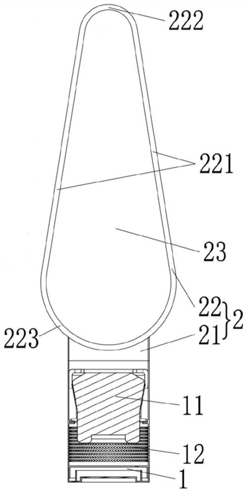
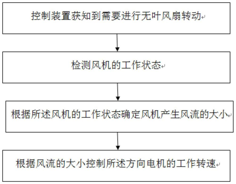
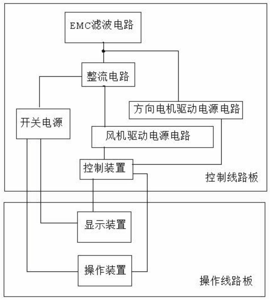
[0031] A bladeless fan, the bladeless fan at least includes a fan used to drive the wind flow and a direction motor to change the wind direction, a control device for controlling the operation of the fan and the direction motor, characterized in that the control When the device controls the direction motor to work, it detects the working state of the fan, determines the wind force of the wind flow generated by the fan according to the working state of the fan, and controls the working speed of the direction motor according to the size of the wind flow.

[0032] Such as figure 1 As shown, in this embodiment, the bladeless fan includes a base 1 and an air outlet 2 located above the base 1 , the base 1 is provided with a fan assembly 11 and an air inlet 12 is provided thereon. The fan assembly is provided with a fan used to drive the wind flow and a direction motor that changes the wind direction by changing the position of the air outlet. The air outlet 2 includes an air inlet 2...


PUM


Abstract

The invention relates to household appliances, in particular to a bladeless fan. The bladeless fan comprises a base and an air outlet piece located above the base, the base internally at least comprises a fan used for driving to generate air flow, an air inlet which is arranged on the base and communicate with the fan and a direction motor used for changing the air direction by changing the position of the air outlet piece, wherein the air outlet piece comprises an air inlet portion connected with the base and an air flow channel which is located above the air inlet portion and communicates with the air inlet portion, the air flow channel is in an annular shape, an air outlet which extends along the air flow channel is further formed in the air flow channel, the bladeless fan further comprises a control device used for controlling the fan and the direction motor to work, when the control device controls the direction motor to work, the working state of the fan is detected, the magnitude of air power of the air flow generated by the fan is determined according to the working state of the fan, and the working rotating speed of the direction motor is controlled according to the magnitude of the air power. The overall physical stability of the bladeless fan is ensured.

Description

technical field [0001] The invention relates to household appliances, in particular to a bladeless fan. Background technique [0002] The fan is a common household device in modern life. The early fans generally adopt the structure of axial flow rotating blades. This type of fan has the characteristics of simple structure and low cost, so it is widely used; Larger, when in use, the rotation of the blades also poses a problem of risk to the elderly and children. [0003] With the improvement of people's living standards, in order to solve the technical problems of traditional axial flow fans, fans with a long strip structure appear as a whole. This type of fan is roughly divided into two types. The basic structure of the known tower fan is a tower-like columnar structure. A motor is installed on the lower part (base) of the fan, and an impeller is installed along the longitudinal direction. The motor drives the impeller to rotate to generate air flow, and then blow out the w...

Claims


Application Information

Patent Timeline
Patent Type & Authority Patents(China)
IPC IPC(8): F04D27/00
CPCF04D27/002F04D27/004
Inventor 周泽煜
Owner 周泽煜
Why Eureka
Try Eureka