
Clamping device of substrate, film formation device, and substrate mounting device and method

A film forming method and substrate holding technology, which is applied in the direction of ion implantation plating, coating, electrical components, etc., can solve the problems of film blurring, mask and substrate adhesion reduction, etc., and achieve the effect of preventing position deviation

Inactive Publication Date: 2018-01-05
CANON TOKKI CORP
View PDF7 Cites 9 Cited by
  • Summary
  • Abstract
  • Description
  • Claims
  • Application Information

AI Technical Summary

Problems solved by technology

[0004] Due to this skew, a gap is generated between the mask and the substrate, and the adhesion between the mask and the substrate is reduced, which causes film blurring, etc.

Method used


Image

  • Clamping device of substrate, film formation device, and substrate mounting device and method
  • Clamping device of substrate, film formation device, and substrate mounting device and method
  • Clamping device of substrate, film formation device, and substrate mounting device and method

Examples


Embodiment approach

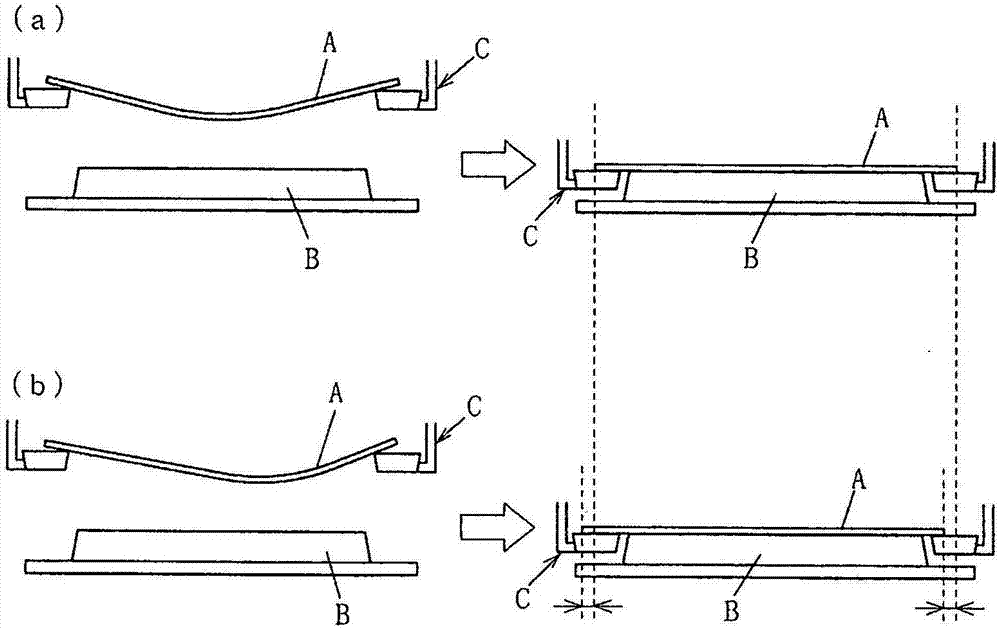
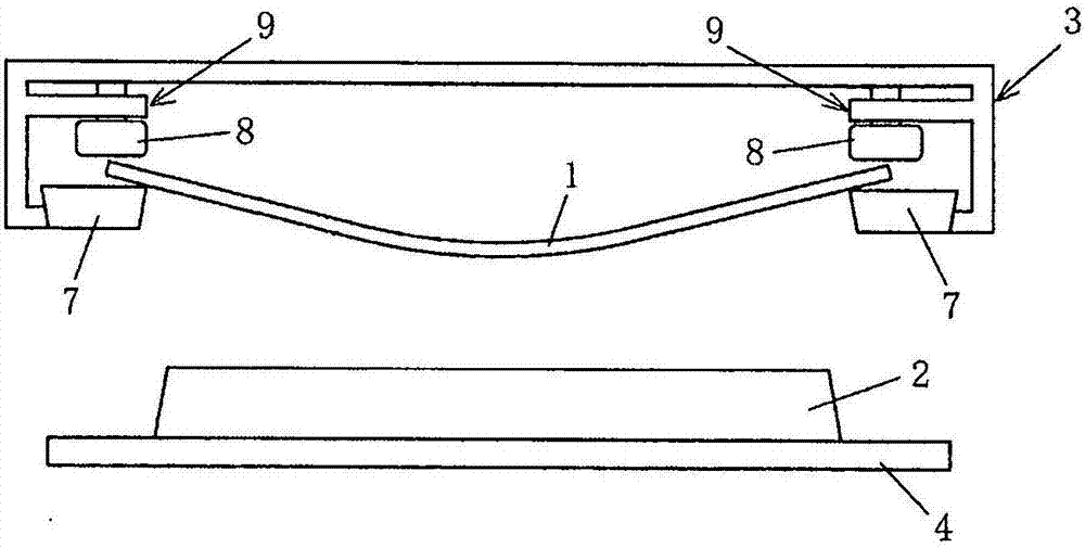
[0032] In the present embodiment, the substrate 1 is lowered and brought into contact with the substrate 1 in a state in which the outer peripheral portion of the substrate 1 is tentatively clamped by the pressing force 8 abutting against the substrate 1 and causing a displacement of the substrate holder 3 . The mask 2 is further lowered to place the substrate 1 on the mask 2 . Thereafter, the pressing force of the pressing tool 8 is set to a stronger pressing force to such an extent that no positional displacement occurs with respect to the substrate holder 3 , and the substrate 1 is actually clamped.

[0033] At this time, at least at the beginning of the contact, the position deviation of the substrate 1 relative to the substrate holder 3 accompanying the contact with the mask 2 is allowed, so the substrate 1 bends due to its own weight and the central part of the substrate 1 comes into contact with the mask 2 in advance. The generated deformation is not hindered, and the o...

Embodiment 1

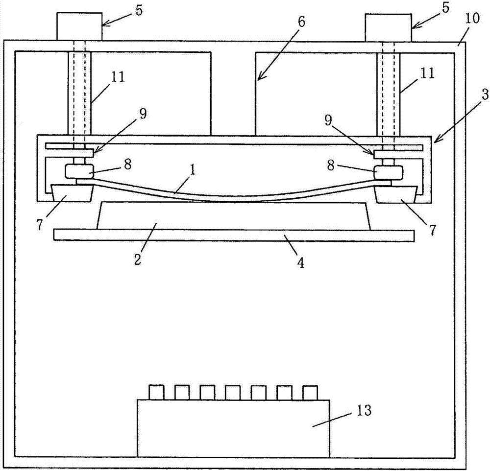
[0038] This embodiment is an example of applying the present invention in a film forming device, such as figure 2 As shown in the figure, in this film forming apparatus, a substrate 1 and a mask 2 are placed in a vacuum chamber 10 and a film is formed using a film forming mechanism including an evaporation source 13 and the like. The film forming device is provided with: a film thickness monitor, which monitors the evaporation rate of the evaporated particles emitted from the evaporation source 13; a film thickness gauge, which is arranged outside the vacuum chamber 10, and converts the amount of monitored evaporated particles into film thickness ; and a power supply for the heater to heat the evaporation source 13 in order to control the evaporation rate of the film-forming material so that the converted film thickness becomes a desired film thickness; and the like. For example, this film-forming apparatus is used in the manufacture of a display panel for an organic electrol...


PUM


Abstract

Provided are a clamping device of a substrate, a film formation device, and a substrate mounting device and method, in which a substrate and a mask can be well attached to each other, the substrate can move steadily and position shifting of the substrate can be prevented when the substrate is mounted on the mask. A substrate mounting process is provided, in which the substrate (1) is mounted on the mask (2) when being pressed and pushed by a press tool (8) on a substrate holding body (3). In terms of the substrate mounting process in which the substrate (1) is pressed and pushed on the substrate holding body (3) by the press tool (8), the substrate is pushed and pressed through press force generated in a way that the press tool (8) is abutted against the substrate (1) at least when the substrate (1) begins contacting the mask (2). After the substrate mounting process, the substrate (1) is pushed and pressed on the substrate holding body (3) by the press tool (8) by means of press forcehigher than force that is produced at the beginning of contact.

Description

technical field [0001] The present invention relates to a substrate clamping method, a substrate clamping device, a film forming method, a film forming device and a manufacturing method of electronic equipment. Background technique [0002] In recent years, substrates have been increased in size and thinned, and the influence of warpage due to the substrate's own weight has increased. In addition, since the film formation region is provided at the central portion of the substrate, the region where the substrate can be held is limited to the outer peripheral portion of the substrate. [0003] Therefore, when the substrate holder supports the outer peripheral portion of the substrate, and the substrate is placed on the mask while the outer peripheral portion (for example, a pair of facing side portions) of the substrate is sandwiched by the substrate holder, the outer peripheral portion is clamped. When the central portion of the substrate being held, which is bent due to the...

Claims


Application Information

Patent Timeline
Patent Type & Authority Applications(China)
IPC IPC(8): C23C14/50C23C14/04C23C14/24C23C14/54H01L51/56
CPCC23C14/50C23C14/042C23C14/24C23C14/54H10K71/164H10K71/166H10K71/00H01L21/187H01L21/67092H01L21/682H10K59/00
Inventor 石井博佐藤智之铃木健太郎
Owner CANON TOKKI CORP
Learn More