Hardware punching mechanism

A hardware and frame technology, applied in the field of hardware punching mechanism, can solve the problems of low punching efficiency, slow effect, uneven edge of the punching place, etc., and achieve good punching effect and high efficiency

Inactive Publication Date: 2018-01-05
DONGGUAN LIANZHOU INTPROP OPERATION MANAGEMENT CO LTD
View PDF7 Cites 7 Cited by
  • Summary
  • Abstract
  • Description
  • Claims
  • Application Information

AI Technical Summary

Problems solved by technology

[0002] When the existing leather, cloth or thin metal parts generally need to be punched, the existing method is to punch holes manually, the punching efficiency is low, the effect is slow, and the edge of the hole is not necessarily uniform, the effect limited

Method used


Image

  • Hardware punching mechanism
  • Hardware punching mechanism

Examples


Embodiment Construction

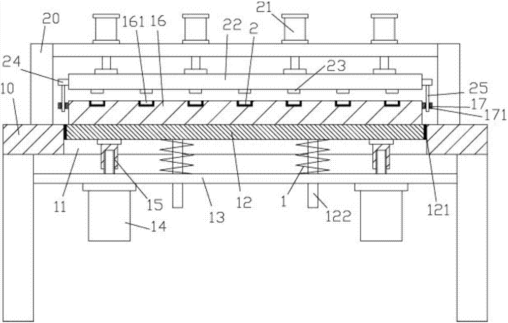
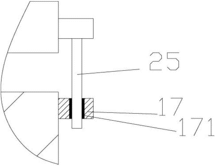
[0014] Examples, see Figure 1 to Figure 2 Shown, a kind of hardware punching mechanism comprises frame 10, and the top surface of the top plate of described frame 10 is fixed with upper support frame 20, and the middle part of the top plate of frame 10 has central through groove 11, and bottom support block 12 inserts Covered in the central through groove 11, the lower horizontal plate 13 is fixed on the two legs of the frame 10, and a plurality of adjusting motors 14 are fixed on the bottom surface of the lower horizontal plate 13, and the output shafts of the adjusting motors 14 pass through the lower horizontal plate 13 and are screwed Adjusting screw sleeve 15 is arranged, and the top of adjusting screw sleeve 15 is fixed on the bottom surface of bottom support block 12, and the top surface of bottom support block 12 is fixed with lower die block 16, and the top face of lower die block 16 has a plurality of positioning punching holes 161 , the top surface of the top plate...


PUM


Abstract

The invention discloses a hardware punching mechanism which comprises a rack; an upper supporting frame is fixed on the top surface of a top plate of the rack; a center through groove is arranged at the middle part of the top plate of the rack; a bottom supporting block is inserted into the center through groove in a sleeved manner; a lower horizontal plate is fixed on two supporting legs of the rack; a plurality of regulation motors are fixed on the bottom surface of the lower horizontal plate; an output shaft of each regulation motor penetrates through the lower horizontal plate and is in screw jointing to a regulation threaded sleeve; the top ends of the regulation threaded sleeves are fixed on the bottom surface of the bottom supporting block; a lower die block is fixed on the top surface of the bottom supporting block; a plurality of positioning stamping holes are formed in the top surface of the lower die block; a plurality of stamping oil cylinders are fixed on the top surface of the top plate of the upper supporting frame; a push rod of each stamping oil cylinder penetrates through the top plate of the upper supporting frame and is fixed on the top surface of an upper pressure block; and a plurality of punches, corresponding to the positioning stamping holes, are arranged on the bottom surface of the upper pressure block. The hardware punching mechanism can punch multiple holes at a time and is good in punching effect and high in punching efficiency.

Description

Technical field: [0001] The invention relates to the technical field of hardware equipment, and more specifically relates to a hardware punching mechanism. Background technique: [0002] When the existing leather, cloth or thin metal parts generally need to be punched, the existing method is to punch holes manually, the punching efficiency is low, the effect is slow, and the edge of the hole is not necessarily uniform, the effect limited. Invention content: [0003] The purpose of the present invention is to overcome the deficiencies of the prior art, and provide a hardware punching mechanism, which can punch multiple holes at one time, and has good punching effect and high efficiency. [0004] The scheme that the present invention solves described technical problem is: [0005] A hardware punching mechanism, comprising a frame, the upper support frame is fixed on the top surface of the top plate of the frame, the middle part of the top plate of the frame has a central t...

Claims


Application Information

Patent Timeline
Patent Type & Authority Applications(China)
IPC IPC(8): B21D28/34
Inventor 杨勇
Owner DONGGUAN LIANZHOU INTPROP OPERATION MANAGEMENT CO LTD
Why Eureka
Try Eureka