
Carding machine and fitting for a carding machine

A carding machine and carding machine technology, applied in fiber treatment, deburring devices, textiles and papermaking, etc., can solve the problems of lifting and maintaining unfavorable fiber materials, poor carding effect, etc., and achieve the effect of reducing agglomeration and optimizing cleaning

Active Publication Date: 2018-01-02
特吕茨施勒集团欧洲公司
View PDF9 Cites 3 Cited by
  • Summary
  • Abstract
  • Description
  • Claims
  • Application Information

AI Technical Summary

Problems solved by technology

However, the disadvantage is that the carding effect is poor, because it is not conducive to achieving a lifting and holding of the fiber material in the carding area.

Method used


Image

  • Carding machine and fitting for a carding machine
  • Carding machine and fitting for a carding machine

Examples


Embodiment Construction

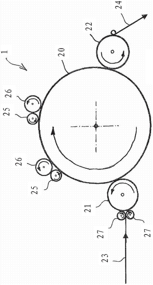
[0023] exist figure 1 A schematic diagram of a carding machine 1 is shown in FIG. 2 , and said carding machine 1 has a main cylinder 20 on which a card clothing with a toothed wire according to the invention is mounted in a manner not shown in detail.

[0024] The licker-in roller 21 cooperates with the main cylinder 20 and conveys the fiber raw material 23 to the licker-in roller 21 via the feed roller 27 . A plurality of stripping rollers 25 and associated working rollers 26 are arranged distributed over the circumference of the main cylinder 20 . The formed web 24 is removed from the main cylinder 20 via a stripping roller 22 .

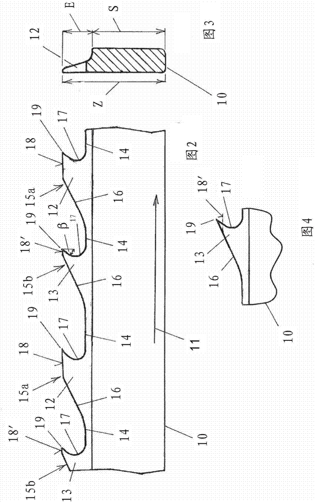
[0025] Use the following figure 2 , image 3 with Figure 4 The described card clothing can be arranged on the main cylinder 20, on the licker-in roller 21 and optionally also on the stripping roller 25, the working roller 26 and the stripping roller 22, wherein the card 1 is only shown as an example And the card clothing according to the inv...


PUM


Abstract

The present invention relates to a fitting for a carding machine (1) for processing textile fibres, and such a carding machine (1), wherein the fitting comprises a saw-tooth wire (10) having teeth (12, 13) configured one behind the other in the running direction of the wire (11), wherein the teeth (12, 13) have an upper profile (15a, 15b) extending over a tooth base (14), which is at least formedfrom the contour of a tooth back (16) and a tooth face (17). According to the invention, the first teeth (12) ,which have a first upper profile (15a), and the second teeth (13), which have a second upper profile (15b) different to the first upper profile (15a), are configured in an alternating manner in the running direction of the wire (11) on the saw-tooth wire (10).

Description

technical field [0001] The invention relates to a card clothing or a card clothing for the processing of textile fibers, which has a sawtooth wire with teeth which are formed successively in the direction of wire run, wherein the teeth There is an upper profile extending over the root of the tooth, said upper profile being formed by at least the profile curves of the tooth back and the tooth front. Background technique [0002] From the document DE 102 54 918 A1 is known a card clothing for a carding machine or a carding machine for processing textile fibers, which card clothing has a saw-toothed wire with teeth that are formed successively in the direction of wire travel. A sawtooth wire, wherein the teeth have an upper profile extending above the root of the tooth, the upper profile consisting of at least the profile curves of the tooth back and tooth front. In this case, the tooth back transitions into a substantially planar top surface and opens into the tooth tip, on t...

Claims


Application Information

Patent Timeline
IPC IPC(8): D01G15/84D01G15/00
CPCD01G15/88
Inventor 沃尔夫冈·希勒
Owner 特吕茨施勒集团欧洲公司
Learn More