Electronic equipment, housing assembly, and circuit board assembly
A technology for circuit board components and electronic equipment, applied in the direction of cooling/ventilation/heating transformation, can solve the problem of limited heat dissipation area, achieve good heat dissipation performance, large heat dissipation area, and solve the effect of heat dissipation
- Summary
- Abstract
- Description
- Claims
- Application Information
AI Technical Summary
Problems solved by technology
Method used
Image

Examples
Embodiment 1
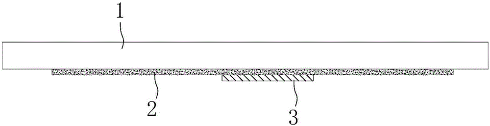
[0026] See figure 1 , the present embodiment provides a casing assembly for electronic equipment, which includes a plastic casing 1, the inner side of the plastic casing 1 is covered with a metal layer 2, and a graphite part is pasted on the metal layer 2 by thermally conductive glue or other thermally conductive materials 3.
[0027] In this embodiment, the metal layer 2 is a metal paint layer, which is coated on the inner surface of the plastic shell 1 . In addition to pasting the above-mentioned graphite component 3 on the metal layer 2 with thermally conductive adhesive, the graphite component 3 can also be fixedly connected to the metal layer 2 through various fixing methods, and the specific fixing method is not limited.
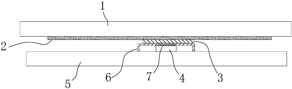
[0028] The shell assembly of this embodiment is assembled on the electronic equipment, and the graphite part 3 on it can be in contact with the heating element 4 in the electronic equipment (see also image 3 ), so that the heat on the heating elemen...
Embodiment 2
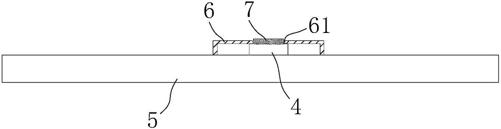
[0035] See Figure 6 , this embodiment provides an electronic device. The difference between this embodiment and Embodiment 1 is that the contact between the graphite component 3 and the thermally conductive adhesive 7 of this embodiment is a concave-convex structure nested with each other, thereby increasing the The contact area between the two speeds up the speed of heat transfer and improves the heat dissipation efficiency. Moreover, the connection through the nested concave-convex structure can prevent the graphite part 3 from moving with the thermally conductive adhesive 7, which is beneficial to ensure the close contact between the two, and at the same time, it is also conducive to the positioning of the two during assembly, thereby improving the assembly process. efficiency.
Embodiment 3
[0037] See Figure 7 This embodiment provides an electronic device. The difference from Embodiment 1 is that the through hole 61 of the shielding cover 6 of this embodiment is opened on the side wall, and the thermally conductive adhesive 7 is pasted on the side of the heating element 4 . The position of the thermally conductive adhesive 7 corresponds to the position of the through hole 61 , so that the thermally conductive adhesive 7 can pass through the through hole 61 . The position of the graphite component 3 also corresponds to the position of the thermal conductive glue 7 , and the graphite component 3 extends in the direction of the thermal conductive glue 7 , so that the thermal conductive glue 7 can be aligned with the graphite component 3 and fully contacted.
[0038] Compared with Embodiments 1 and 2, the graphite component 3 of this embodiment is not stacked together with the thermally conductive adhesive 7 , which is beneficial to make the electronic device thinne...
PUM
 Abstract
Description
Claims
Application Information
 - Generate Ideas
- Intellectual Property
- Life Sciences
- Materials
- Tech Scout
- Unparalleled Data Quality
- Higher Quality Content
- 60% Fewer Hallucinations
Browse by: Latest US Patents, China's latest patents, Technical Efficacy Thesaurus, Application Domain, Technology Topic, Popular Technical Reports.
© 2025 PatSnap. All rights reserved.Legal|Privacy policy|Modern Slavery Act Transparency Statement|Sitemap|About US| Contact US: help@patsnap.com