A lift driven by a hydraulic cylinder

A hydraulic cylinder and lift technology, which is applied in the field of electromechanical equipment, can solve the problems of large space and high cost of the lift, and achieve the effects of strong lifting capacity, flexible use, and small size

Inactive Publication Date: 2018-12-04
CHONGQING COLLEGE OF ELECTRONICS ENG
View PDF6 Cites 0 Cited by
  • Summary
  • Abstract
  • Description
  • Claims
  • Application Information

AI Technical Summary

Problems solved by technology

[0003] Aiming at the above-mentioned deficiencies in the prior art, the main purpose of the present invention is to solve the problem that the current lifts occupy a large space and are expensive to manufacture, and provide a small and flexible hydraulic cylinder-driven lift

Method used


Image

  • A lift driven by a hydraulic cylinder
  • A lift driven by a hydraulic cylinder
  • A lift driven by a hydraulic cylinder

Examples


Embodiment Construction

[0027] The present invention will be further described below in conjunction with the accompanying drawings and specific embodiments.

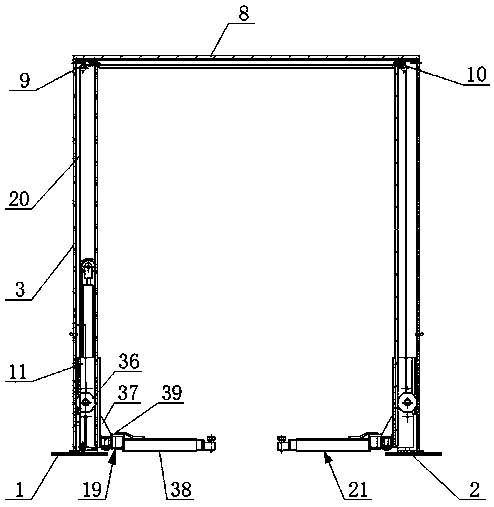
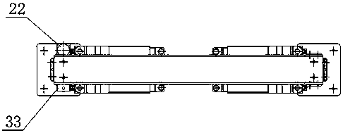
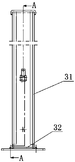
[0028] Such as Figure 1-Figure 11 As shown, a hydraulic cylinder-driven lift of the present invention includes a left base 1 and a right base 2, and a bracket assembly 3 is installed between the left base 1 and the right base 2, and the bracket assembly 3 is It consists of a door-shaped bracket 31 and a base plate 32 fixed at the bottom of the bracket 31. The two ends of the bracket 31 are respectively fixed on the left base 1 and the right base 2 through the corresponding base plate 32; there is a detection hole in the middle of the side of the bracket 31 4. On the bracket 31 below the detection hole 4, a lock block mounting plate 5 is fixed with a hexagon socket head cap screw, and a self-locking block 6 is hinged on the lock block mounting plate 5, and a self-locking block is installed at the edge of the detection hole 4. Magnet 7, the sel...


PUM


Abstract

The invention discloses a lifting machine based on hydraulic cylinder drive. The lifting machine comprises a left base and a right base and is characterized in that a support assembly is mounted between the left base and the right base, the support assembly comprises a door-shaped support and bottom plates fixed at the bottom of the support, and two ends of the support are fixed on the left base and the right base through corresponding bottom plates; a detection hole is arranged in the middle of the lateral side of the support, a locking block mounting plate is fixed on the support below the detection hole through socket head cap screws, a self-locking block is hinged to the locking block mounting plate, a self-locking magnet is mounted at the edge of the detection hole, and the self-locking block rotates under the attracting force of the self-locking magnet and covers the detection hole; a crossbeam is mounted at the top of the support assembly, a left pulley assembly is mounted at the bottom of the left side of the crossbeam, a right pulley assembly is mounted at the bottom of the right side of the crossbeam, and a hydraulic cylinder assembly is mounted at the bottom of the left side of the support assembly. The lifting machine is small in size, flexible to use and good in safety.

Description

technical field [0001] The invention relates to a large-scale electromechanical equipment, in particular to a lift driven by a hydraulic cylinder, and belongs to the technical field of electromechanical equipment. Background technique [0002] Car lift refers to the car maintenance equipment used for car lifting in the car maintenance industry. Lifts play a vital role in vehicle maintenance and maintenance. No matter whether the vehicle is overhauled or minor repairs, it is inseparable from it. The nature and quality of its products directly affect the personal safety of maintenance personnel. In the repair and maintenance enterprises of different sizes, whether it is a comprehensive repair shop that repairs a variety of models, or a street shop with a single business scope, almost all of them are equipped with lifts. The current car lifts mainly include two-post lifts, four-post lifts, and scissor lifts. Although these types of lifts can meet the lifting needs, most of the...

Claims


Application Information

Patent Timeline
Patent Type & Authority Patents(China)
IPC IPC(8): B66F7/04B66F7/28
CPCB66F7/04B66F7/28
Inventor 钟瑜
Owner CHONGQING COLLEGE OF ELECTRONICS ENG
Why Eureka
Try Eureka