
Model test piece design method of metal-wing main box section bending rigidity test

A technology of model test and design method, applied in the field of aircraft structure rigidity test, can solve the problems of long production and test cycle, large test piece size and high test conditions, and achieve the effect of shortening design cycle, saving design cost and low production cost

Active Publication Date: 2017-12-26
XIAN AIRCRAFT DESIGN INST OF AVIATION IND OF CHINA
View PDF9 Cites 1 Cited by
  • Summary
  • Abstract
  • Description
  • Claims
  • Application Information

AI Technical Summary

Problems solved by technology

However, this method of using the actual aircraft wing main box section as a test piece to test the bending stiffness of the aircraft wing main box section cannot realize the rapid iteration of large-scale aircraft wing main box section design-bending stiffness acquisition, and cannot be used in the aircraft design process. In this method, the bending stiffness can be obtained quickly and guide the stiffness design of the wing main box section; in addition, the actual wing main box section is used as the test piece for the stiffness test. High disadvantage
[0003] For the bending stiffness test of the wing main box section of a large aircraft, it is also possible to quickly test the bending stiffness of the model test piece scaled to the wing main box section. Compared with the real wing main box section test piece, this The scaled test piece has the advantages of small size, short production and test period, low test conditions and low test cost. However, due to the small size of the long stringer of the wing stiffened wall plate, it is difficult to process and manufacture, which often limits the scale of the test piece. Proportion

Method used


Image

  • Model test piece design method of metal-wing main box section bending rigidity test
  • Model test piece design method of metal-wing main box section bending rigidity test
  • Model test piece design method of metal-wing main box section bending rigidity test

Examples


Embodiment Construction

[0039] In order to make the objectives, technical solutions and advantages of the present invention clearer, the technical solutions in the embodiments of the present invention will be described in more detail below in conjunction with the drawings in the embodiments of the present invention.

[0040] The model test piece design method for the rigidity test of the aircraft metal wing main box section of the present invention is suitable for the design of the large aircraft metal wing main box section, and it is the first time that a model test piece using an equivalent wing wall plate is used to reversely obtain an actual large aircraft The method of bending stiffness of the main box section of the metal wing realizes the test of the bending stiffness of the main box section of the metal wing of a large aircraft through the model test piece, and solves the problem of large size of the stiffness test piece of the main box section of the metal wing of a large aircraft, a long prod...


PUM


Abstract

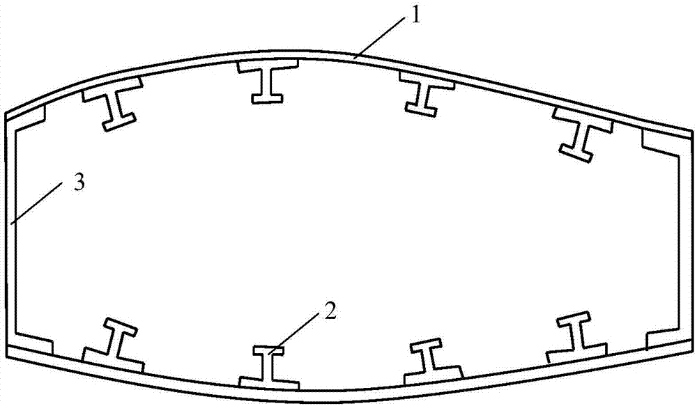
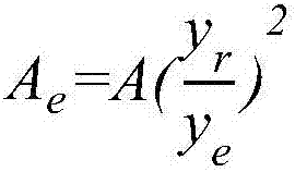
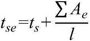
The invention relates to a model test piece design method of a metal-wing main box section bending rigidity test. The method comprises the following steps of according to a real aircraft metal wing main box section, acquiring a stringer equivalent area Ae and an equivalent skin thickness tse in a real aircraft; according to the real aircraft metal wing main box section, acquiring a minimum thickness td of a wing spar in the real aircraft, according to a model test piece processing method, acquiring a minimum thickness ta which can be processed by a model test piece, and according to the td and the ta, determining a scaling n of the model test piece; simplifying a real aircraft wing main box section structure to acquire a real aircraft wing main box section simplification structure, and according to the real aircraft wing main box section simplification structure and the scaling, acquiring a model test piece structure; and through carrying out rigidity testing on the model test piece structure, acquiring that bending rigidity of the model test piece is EIm, and according to the bending rigidity of the model test piece and a minimum scaling, acquiring bending rigidity EIo of the real aircraft metal wing main box section. The method is simple and high-efficient, cost is saved and there are other advantages.

Description

technical field [0001] The invention belongs to the technical field of aircraft structure stiffness test, in particular to a design method of a model test piece for testing the bending stiffness of a metal wing main box section. Background technique [0002] For the bending stiffness test of the wing main box section of large aircraft, the real wing main box section is used as the test piece at home and abroad, and the bending stiffness of the actual wing main box section is obtained by measuring the bending stiffness of the real wing main box section stiffness. The real wing main box section is used as the test to measure the bending stiffness of the real wing main box section. This method is very direct. The measured bending stiffness is the bending stiffness of the actual aircraft wing main box section. Both domestic and foreign large aircraft are This method is used to obtain the bending stiffness of the main box section of the actual aircraft wing. However, this metho...

Claims


Application Information

Patent Timeline
IPC IPC(8): G01M5/00
CPCG01M5/0016
Inventor 赵占文周银华柴慧刘存
Owner XIAN AIRCRAFT DESIGN INST OF AVIATION IND OF CHINA
Learn More