Hydraulic stop valve and application method

A shut-off valve and hydraulic technology, applied in valve details, valve devices, valve operation/release devices, etc., can solve the problems of complex structure, large load of valve body, large volume, etc., achieve simple structure, prolong service life, open The effect of small torque

Pending Publication Date: 2017-12-26
XIAN AIRCRAFT IND GROUP
View PDF6 Cites 2 Cited by
  • Summary
  • Abstract
  • Description
  • Claims
  • Application Information

AI Technical Summary

Problems solved by technology

The structure of the valve body in the prior art controls the opening and closing of the valve body through hydraulic pressure, causing a large load on the valve body, which affects the overall working stability and efficiency
At the same time, due to its complex structure and large volume in production, both the convenience of installation and use and the difficulty of maintenance will cause inconvenience to production

Method used


Image

  • Hydraulic stop valve and application method
  • Hydraulic stop valve and application method
  • Hydraulic stop valve and application method

Examples


Embodiment Construction

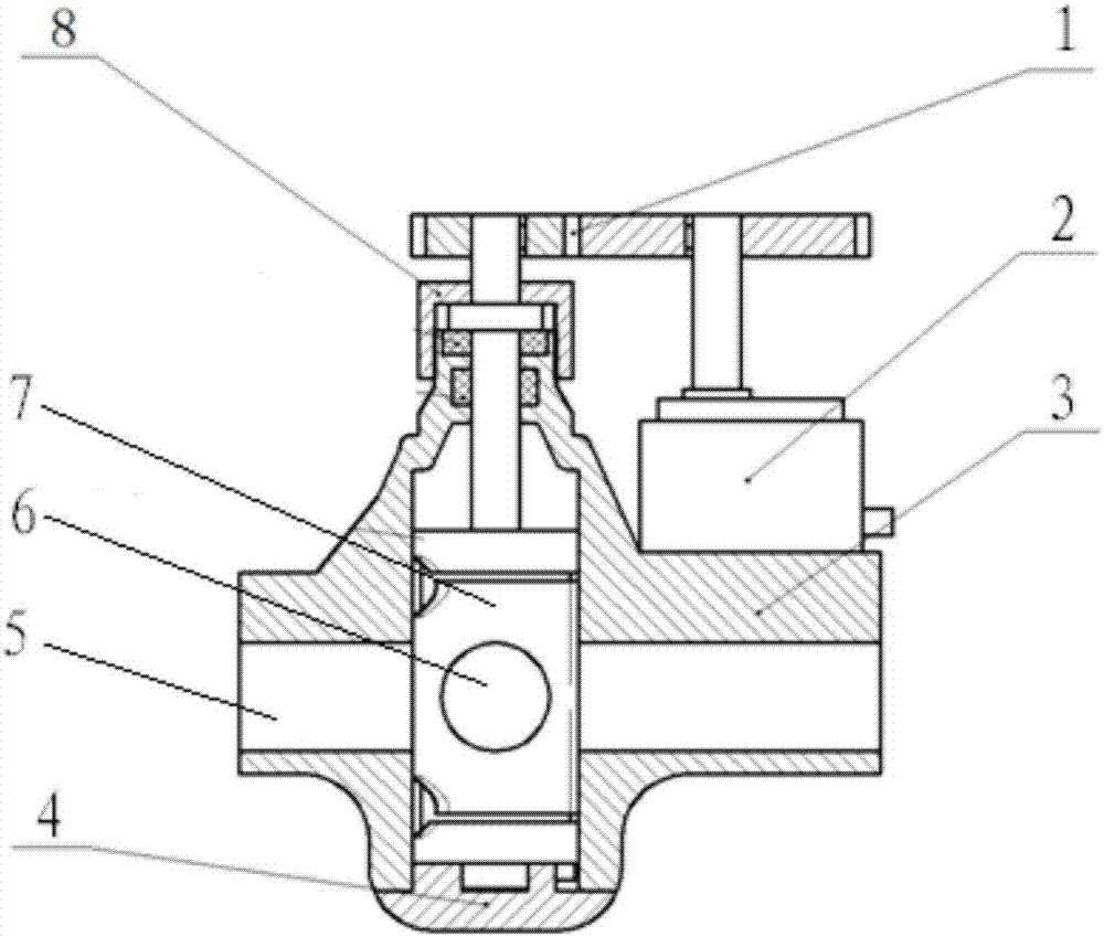
[0020] With reference to the drawings, this application is a hydraulic stop valve, which contains a valve body 3, a valve core 7, a base 4 and a gland 8. The valve body 3 has a horizontal liquid passage 5 and a longitudinal valve core cavity 9, so The said valve core 7 is embedded in the valve core cavity 9 of the valve body 3. The middle part of the valve core 7 is a cylindrical valve core body. Both ends of the valve core body are protruding valve core shafts 14, and there are protruding valve core shafts 14 in the middle of the valve core body. The through hole 6 for liquid flow in the horizontal direction is provided with an annular diversion groove 11 on the upper and lower surfaces of the valve core body. The side surface of the valve core body perpendicular to the direction of the through hole 6 has a longitudinal diversion groove connected to the annular diversion groove. Groove 10, on the other side surface of the valve core body, the upper and lower annular diversion g...


PUM


Abstract

The invention discloses a hydraulic stop valve and an application method. The hydraulic stop valve comprises a valve body, a valve element, a base and a steering engine; the valve body is provided with a transverse liquid channel and a longitudinal valve element cavity; the valve element is embedded in the valve element cavity of the valve body; a transverse through hole for enabling liquid to circulate is formed in the middle part of the valve element body; the valve element body is provided with an annular guide groove, a longitudinal guide groove and a communicating balance groove; a projected eccentric positioning block is arranged at the bottom of the valve element body, and is matched with the base; the steering engine is fixed on the valve body; an output shaft of the steering engine is connected with a valve element shaft at the upper end of the valve element through a transmission gear; the hydraulic stop valve is connected to a liquid pipeline; the steering engine is connected with a remote control system; and the remote control system controls the rotating speed and the rotating angle of the steering engine through electric signals.

Description

Technical field [0001] This application relates to hydraulic circulation technology, and is particularly suitable for electric shut-off valves for hydraulic system liquid pipelines and their use methods. Background technique [0002] The dexterity and electric control of hydraulic system components are the development trend of mechatronics and hydraulic integration. The automation, unmanned and remote control of the hydraulic system through electronic control is the main way to apply modern hydraulic principles. While realizing functions, it is necessary to pay more attention to the performance and quality requirements of the product. At the same time, the convenience and aesthetics of the product are also products. A more competitive logo. Most of the common hydraulic shut-off valves use manual control structure or use external piston cylinder transmission structure. The external piston cylinder structure will be equipped with a hydraulic cylinder in the valve itself, and the h...

Claims


Application Information

Patent Timeline
IPC IPC(8): F16K5/04F16K5/08F16K31/04F16K31/53
CPCF16K5/0407F16K5/08F16K31/043F16K31/535
Inventor 庞龙飞魏晓彪马鑫
Owner XIAN AIRCRAFT IND GROUP
Why Eureka
Try Eureka