Servo valve needle hot runner system

A technology of hot runner and valve needle, applied in the field of servo valve needle hot runner system, can solve the problems of large glue flow, economic loss, affecting product molding quality and molding cycle, etc., to achieve precise control and avoid asynchronous effects

Pending Publication Date: 2017-12-26
喻铁军
View PDF5 Cites 1 Cited by
  • Summary
  • Abstract
  • Description
  • Claims
  • Application Information

AI Technical Summary

Problems solved by technology

[0002] In the actual production of existing plastic molds, the runners of the mold have two forms: cold runners and hot runners; among them, there are two types of hot runners: open hot runners and needle valve hot runners. Its characteristics, but the needle valve type hot runner has the characteristics of large glue flow, convenient glue sealing, and not easy to be drawn; most of the needle valve control methods on the market currently use cylinders or oil cylinders to drive the opening and closing of the needle valve , when used in a multi-cavity plastic mold, there will be problems such as the cylinder piston cannot be opened and closed effectively or the opening and closing are not synchronized due to the instability of air pressure or oil pressure or internal leakage of the cylinder, resulting in the inability to open the flow channel or flow The road glue is unstable, which affects the product molding quality and molding cycle, causing major economic losses

Method used


Image

  • Servo valve needle hot runner system
  • Servo valve needle hot runner system

Examples


Embodiment Construction

[0014] The specific implementation manners of the present invention will be described in further detail below in conjunction with the accompanying drawings.

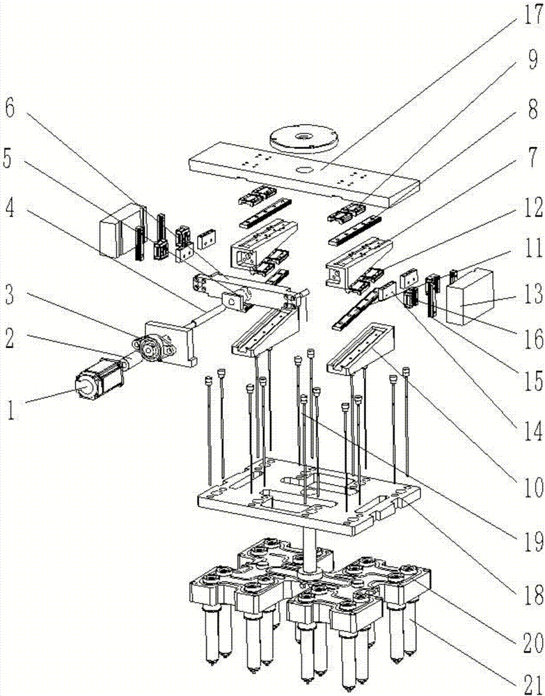
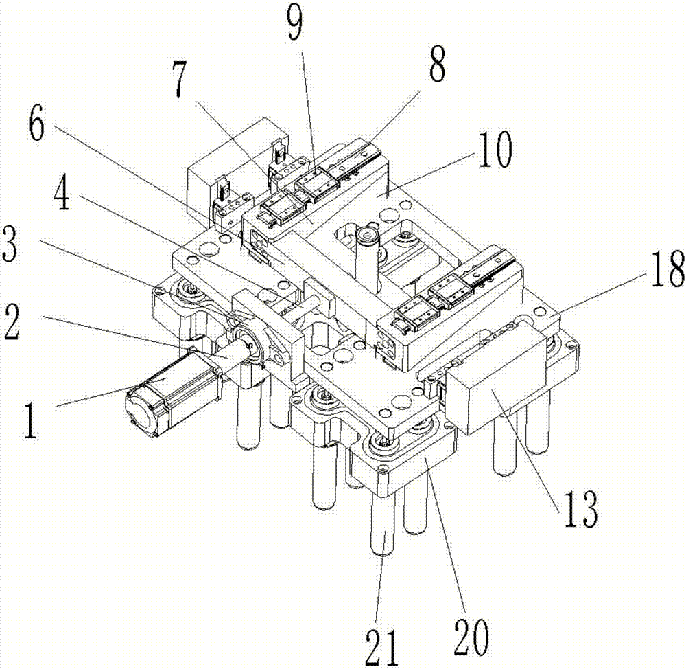
[0015] See attached figure 1 -2, the present invention includes a servo motor 1, a valve needle fixing plate 18 and a manifold 20, the manifold 20 is provided with a plurality of hot nozzles 21, the drive shaft of the servo motor 1 is connected to one end of the coupling 2, and the coupling 2 The other end is connected with the ball screw 4, the ball screw 4 is supported and installed on the bearing seat 3 and the ball screw nut 5, the ball screw nut 5 is installed on the main push plate 6, the drive shaft and coupling of the servo motor 1 2 coincides with the axis of the ball screw 4, the main push plate 6 is provided with a screw hole, the ball screw 4 matches the screw hole on the main push plate 6, and the main push plate 6 is connected with two upper push plates 7, Two lower push plates 10 are installed on the need...


PUM


Abstract

The invention discloses a servo valve needle hot runner system. The servo valve needle hot runner system is characterized by comprising a servo motor, a valve needle fixing plate and a splitter plate; a plurality of hot nozzles are arranged on the splitter plate; a driving shaft of the servo motor is connected with one end of a coupler, and the other end of the coupler is connected with a ball screw; the ball screw is supported and installed on a bearing block and a ball screw nut; the ball screw nut is installed on a main pushing plate; the axes of the driving shaft of the servo motor, the coupler and the ball screw coincide with one another; the main pushing plate is provided with a screw hole; the ball screw is matched with the screw hole in the main pushing plate; the main pushing plate is connected with two upper pushing plates; two lower pushing plates are installed on the valve needle fixing plate; the lower surface of each upper pushing plate and the upper surface of each lower pushing plate both are oblique faces with the inclination angle being 10-60 degrees; the oblique faces of the lower pushing plates are provided with grooves; lower guide rails are installed in the grooves; two lower sliding blocks are installed on the oblique faces of the upper pushing plates; and the main pushing plate drives the lower sliding blocks to slide on the guide rails through rotation of the ball screw.

Description

technical field [0001] The invention relates to the field of injection mold hot runner systems, in particular to a servo valve needle hot runner system. Background technique [0002] In the actual production of existing plastic molds, the runners of the mold have two forms: cold runners and hot runners; among them, there are two types of hot runners: open hot runners and needle valve hot runners. Its characteristics, but the needle valve type hot runner has the characteristics of large glue flow, convenient glue sealing, and not easy to be drawn; most of the needle valve control methods on the market currently use cylinders or oil cylinders to drive the opening and closing of the needle valve , when used in a multi-cavity plastic mold, there will be problems such as the cylinder piston cannot be opened and closed effectively or the opening and closing are not synchronized due to the instability of air pressure or oil pressure or internal leakage of the cylinder, resulting in...

Claims


Application Information

Patent Timeline
Patent Type & Authority Applications(China)
IPC IPC(8): B29C45/27B29C45/28
CPCB29C45/27B29C45/2806B29C45/281B29C2045/2813
Inventor 喻铁军
Owner 喻铁军
Why Eureka
Try Eureka