
Pneumatic adjustable remote center compliance device

A pneumatic and compliant technology, applied in metal processing, metal processing equipment, manufacturing tools, etc., can solve the problems of increasing the inertia of the assembly system, increasing the mass and volume of the compliant device, and being unable to apply to occasions where the size of the parts is variable, to ensure Efficient execution and the effect of increasing adaptability

Active Publication Date: 2017-12-26
SHANGHAI JIAO TONG UNIV
View PDF9 Cites 4 Cited by
  • Summary
  • Abstract
  • Description
  • Claims
  • Application Information

AI Technical Summary

Problems solved by technology

[0003] Most of the existing far-center compliance devices use elastic units with fixed structural dimensions and flexible characteristics. The end compliance center and lateral / axial compliance of the entire device cannot be changed, so it cannot be applied to occasions where the part size is variable
On this basis, an adjustable far-center compliance device has been developed, most of which use mechanical motion to adjust the stiffness parameters or layout parameters of the elastic unit, so as to realize the position adjustment of the end compliance center of the compliance device, but the mechanical adjustment method It is necessary to use a rigid body mechanism as an auxiliary, which will not only increase the mass and volume of the compliance device, reduce the flexibility of the assembly operation, but also increase the inertia of the assembly system, making real-time rapid control difficult

Method used


Image

  • Pneumatic adjustable remote center compliance device
  • Pneumatic adjustable remote center compliance device
  • Pneumatic adjustable remote center compliance device

Examples


Embodiment 1

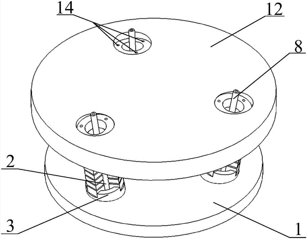
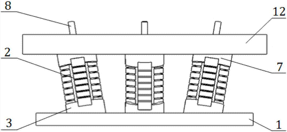
[0035] Such as figure 1 with figure 2 As shown, this embodiment includes: a moving platform 1, three adjustable elastic units 2 and a fixed platform 12, wherein: the moving platform 1 and the fixed platform 12 are arranged up and down oppositely, and the adjustable elastic unit 2 is used to fix the center of circle of the outer end surface of the platform 12 A circumferential ring array is used as the center, and it is arranged obliquely between the moving platform 1 and the fixed platform 12;

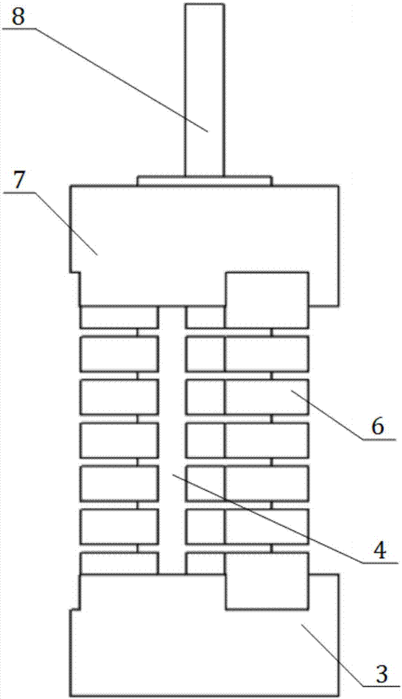
[0036] Such as image 3 , Figure 4 with Figure 8 As shown, the adjustable elastic unit 2 includes: an upper base 7 arranged coaxially, a lower base 3, a three-lobed multi-chamber adjustable elastic structure 4, a laminated elastic structure 9 and an air path joint 8, wherein: There are three airway grooves 19 outside the circumference of the laminated elastic structure 9. The three-petal multi-lumen adjustable elastic structure 4 is sleeved and fixed on the laminated elastic str...


PUM


Abstract

The invention belongs to the technical field of mechanical assembling and discloses a pneumatic adjustable remote center compliance device. The device comprises a fixed platform, a plurality of adjustable elastic units and a moving platform, wherein the fixed platform and the moving platform are arranged oppositely up and down, the adjustable elastic units are arranged obliquely between the fixed platform and the moving platform in a circumferential annular array mode with the circle center of the outer side end surface of the fixed platform as the center. Each adjustable elastic unit comprises an upper base, a lower base, a petal-type multi-cavity adjustable elastic structure, a stacked elastic structure and a gas channel nipple which are arranged coaxially, wherein the petal-type multi-cavity adjustable elastic structure is fixed to the stacked elastic structure in a sleeving mode to form a plurality of gas channels, the upper end and the lower end of the petal-type multi-cavity adjustable elastic structure are sleeved with the upper base and the lower base correspondingly in a sealed mode, and the gas channel nipple is fixedly connected with the upper base and connected with the gas channels. According to the pneumatic adjustable remote center compliance device provided by the invention, by additionally arranging a gas actuating structure, the universality of the compliance device is improved, and requirements of assembling operation for a series of shaft holes of various sizes can be met.

Description

technical field [0001] The invention relates to a technology in the field of mechanical assembly, in particular to a pneumatic adjustable remote-center compliance device. Background technique [0002] In automated assembly operations, the existence of various errors can easily cause jamming between parts to be assembled. In engineering practice, positioning compensation and error correction of assembly robots are often used to solve such problems. At present, robot error compensation is mainly realized through compliant operation, including active compliant and passive compliant methods. Although passive compliance devices have problems such as low precision and poor controllability, they have the advantages of fast response speed, simple structure and control, etc., which are of great significance for industrial automation production. In addition, the compliant operation of the passive compliant device is not limited by the tolerance requirements of the parts to be assembl...

Claims


Application Information

Patent Timeline
IPC IPC(8): B23P19/00
CPCB23P19/00
Inventor 王皓潘浩赵勇余海东余觉
Owner SHANGHAI JIAO TONG UNIV
Learn More