
New energy automobile apparatus

A new energy vehicle, sliding installation technology, applied in the direction of coupling devices, electric vehicles, electric vehicle charging technology, etc., can solve problems such as unstable power supply connection, damage to new energy vehicles, and detachment of charging guns, so as to increase the safety of electricity use , low production cost, simple results

Inactive Publication Date: 2017-12-19
叶孟杰
View PDF3 Cites 4 Cited by
  • Summary
  • Abstract
  • Description
  • Claims
  • Application Information

AI Technical Summary

Problems solved by technology

[0002] At present, the charging of new energy vehicles is mainly to insert the charging gun connected to the new energy vehicle directly into the charging pile body. Although this cooperation method is simple to operate, the charging gun can still be pulled out directly after being inserted into the charging pile body. , when accidentally kicking and bumping into the cable connected between the charging gun and the new energy vehicle, it will cause the charging gun to be separated from the charging pile body, resulting in a sudden power failure of the new energy vehicle, so the existing cooperation There is a risk of unstable power supply connection in this way, which may cause sudden power failure and damage to new energy vehicles

Method used


Image

  • New energy automobile apparatus
  • New energy automobile apparatus
  • New energy automobile apparatus

Examples


Embodiment Construction

[0021] All the features disclosed in this specification, or all disclosed methods or steps in the process, except for mutually exclusive features and / or steps, can be combined in any manner.

[0022] Any feature disclosed in this specification (including any appended claims, abstract and drawings), unless specifically stated, can be replaced by other equivalent or equivalent alternative features. That is, unless otherwise stated, each feature is just one example of a series of equivalent or similar features.

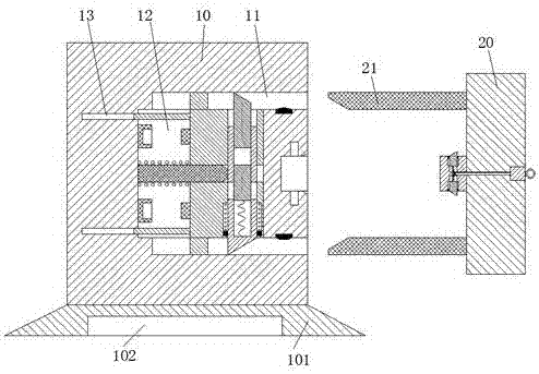
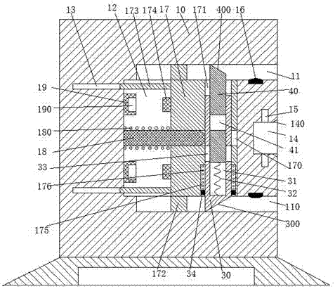
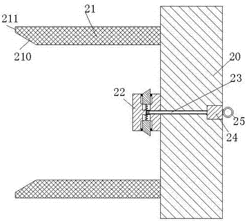
[0023] Such as Figure 1 to Figure 6 As shown, a new energy vehicle device of the device of the present invention includes a charging pile body 10 and a charging gun 20 connected to the new energy vehicle. The bottom end of the charging pile body 10 is fixedly installed with a base 101, and the base 101 is installed There is a counterweight 102, a middle groove 14 is provided in the middle of the right end surface of the charging pile body 10, a locking groove 15 is provided...


PUM


Abstract

The invention discloses a new energy automobile apparatus. The new energy automobile apparatus comprises a charging pile body and a charging gun connected with a new energy automobile; a base is fixedly mounted on the bottom end plane of the charging pile body; a weight balancing block is mounted in the base; a middle groove is formed in the middle part of the right end plane of the charging pile body; locking grooves are symmetrically formed in the upper and lower end walls of the middle groove; a first inclined plane is arranged at the right end of the middle groove; an upper inserting-connecting groove and a lower inserting-connecting groove are symmetrically formed in the charging pile body; power connection collision blocks are mounted on both of the end planes, close to the middle groove, of the upper inserting-connecting groove and the lower inserting-connecting groove respectively; a sliding-moving cavity which extends left and right and is connected with the upper inserting-connecting groove and the lower inserting-connecting groove is formed in the charging pile body; a sliding-moving frame which can slide left and right is mounted in the sliding-moving cavity; and a first sliding-moving groove connected left and right and a second sliding-moving groove connected up and down are formed in the sliding-moving frame.

Description

Technical field [0001] The invention relates to the field of electricity consumption for household new energy vehicles, in particular to a new energy vehicle device. Background technique [0002] At present, the charging of new energy vehicles is mainly by directly inserting the charging gun connected with the new energy vehicle into the charging pile body. Although this matching method is simple to operate, the charging gun can be directly pulled out after being inserted into the charging pile body. , When the accidental kick hits the cable connecting the charging gun and the new energy vehicle, it will cause the charging gun to separate from the charging pile body, resulting in a sudden power failure of the new energy vehicle, so the existing cooperation This method has the risk of unstable power supply connection, which is likely to cause sudden power failure and damage to new energy vehicles. Summary of the invention [0003] In view of the above technical deficiencies, the p...

Claims


Application Information

Patent Timeline
Patent Type & Authority Applications(China)
IPC IPC(8): H01R13/703H01R13/627B60L11/18
CPCB60L53/16B60L53/31H01R13/6275H01R13/7035H01R2201/26Y02T10/70Y02T10/7072Y02T90/12Y02T90/14
Inventor 叶孟杰
Owner 叶孟杰
Learn More