
A self-calibration method for road surveillance cameras using road surface information

A surveillance camera and video camera technology, applied in the field of information technology visual processing, can solve the problems of many parameters in the VVW algorithm formula and difficult parameter identification, and achieve the effect of simple algorithm rules, low formula complexity, and easy implementation.

Inactive Publication Date: 2020-01-14
CHANGAN UNIV
View PDF5 Cites 0 Cited by
  • Summary
  • Abstract
  • Description
  • Claims
  • Application Information

AI Technical Summary

Problems solved by technology

It can be seen that the VVW algorithm formula has many parameters and is highly nonlinear, so it is difficult to identify the parameters

Method used


Image

  • A self-calibration method for road surveillance cameras using road surface information
  • A self-calibration method for road surveillance cameras using road surface information
  • A self-calibration method for road surveillance cameras using road surface information

Examples


Embodiment Construction

[0033] The present invention will be further described below by means of the accompanying drawings and examples.

[0034] This embodiment provides a method for self-calibrating a road monitoring camera using road surface information, comprising the following steps:

[0035] Step 1, determine the relationship between the world coordinate system and the image coordinate system;

[0036] Use the camera to take the road image of the road, and find two vanishing points in the road image. The two vanishing points refer to a point in the road image where the road converges at infinity along the road extension direction and the infinite distance perpendicular to the road extension direction. The point where the ends converge, let the coordinates of the two vanishing points in the world coordinate system be x 0 =[-tanθ 1 0 0] T , x 1 =[1 tanθ 0 0] T , θ is the rocking angle of the camera, and the coordinates of the two vanishing points are converted from the world coordinate system...


PUM

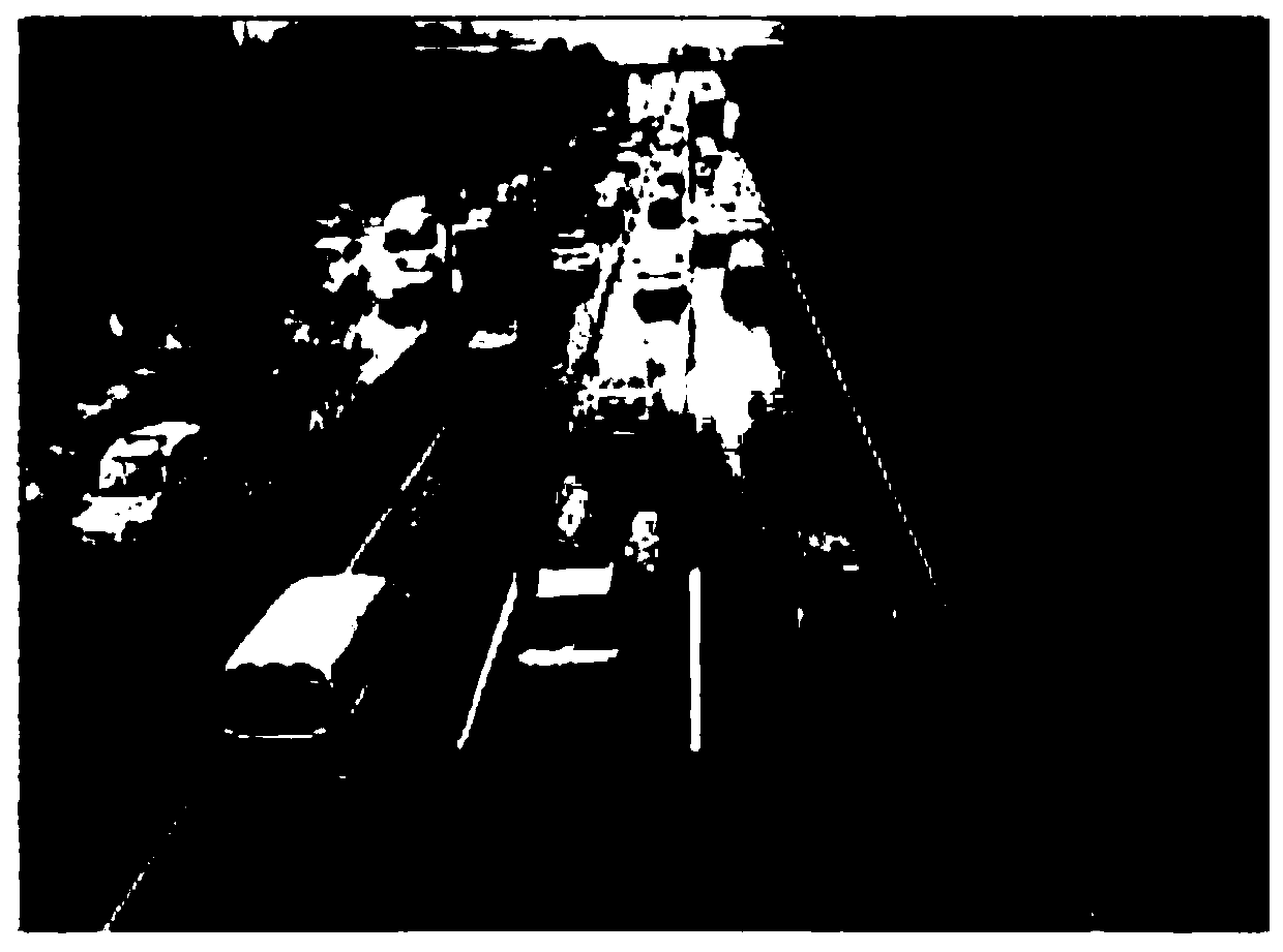

Abstract

The invention belongs to the technical field of road information camera self-calibration, and particularly relates to a road monitoring camera self-calibration method of utilizing road surface information. The method finally obtains scientific and reasonable formula parameters through a series of formula derivation and experiment data collection on the basis of a vanishing point, road width and road dotted-line length, and includes the following steps: 1) determining a homography matrix of a camera space model; 2) using parameters, which are determined the in step 1), to obtain initial internal parameters of the camera through conversion formulas of the vanishing point between 3D homogeneous coordinates and image coordinates; and 3) using the three external parameters, the road width, the dotted-line length and the vanishing point, of the camera on the basis of the step 2) to further use simultaneous equation derivation formulas to obtain more accurate and precise internal parameters of the camera. Through the method for identification, the internal parameters of the camera can be highly efficiently and quickly identified; and the method is easy to realize, and high in robustness.

Description

technical field [0001] The invention belongs to the technical field of visual processing of information technology, and in particular relates to a self-calibration method of a road monitoring camera using road surface information. Background technique [0002] As the cost of cameras and processors continues to drop, vision-based sensing is becoming an increasingly popular alternative to traditional sensors for collecting traffic data. Many research and commercial systems have obtained a series of information we are interested in through video analysis, such as road occupancy, vehicle speed, vehicle type, event detection, etc. Besides cost, vision systems are particularly attractive due to their non-intrusive and rich data collection capabilities. [0003] In order for a vision-based system to measure the speed of a vehicle, there must be a mapping from pixels in the image to world coordinates. This mapping can also be used to improve the accuracy of estimates for other typ...

Claims


Application Information

Patent Timeline
Patent Type & Authority Patents(China)
IPC IPC(8): G06T7/80
CPCG06T7/80G06T2207/30232G06T2207/30236
Inventor 王伟程钰清
Owner CHANGAN UNIV
Learn More