Thread clamp

A technology of clamping and loading devices, which can be used in transportation and packaging, textiles and papermaking, thin material processing, etc., and can solve problems such as dirt sensitivity

Active Publication Date: 2017-12-19
SAURER COMPONENTS GMBH
View PDF9 Cites 4 Cited by
  • Summary
  • Abstract
  • Description
  • Claims
  • Application Information

AI Technical Summary

Problems solved by technology

[0033] The above-mentioned clamping devices have proven to be more or less effective, but are still relatively sensitive to dirt, especially since their centrifugal force element is designed as a movably mounted ball
This means that there is a lot of room for improvement of known thread clamping devices (with regard to providing correct operation as long as possible without any disturbances)

Method used


Image

  • Thread clamp
  • Thread clamp
  • Thread clamp

Examples


Embodiment Construction

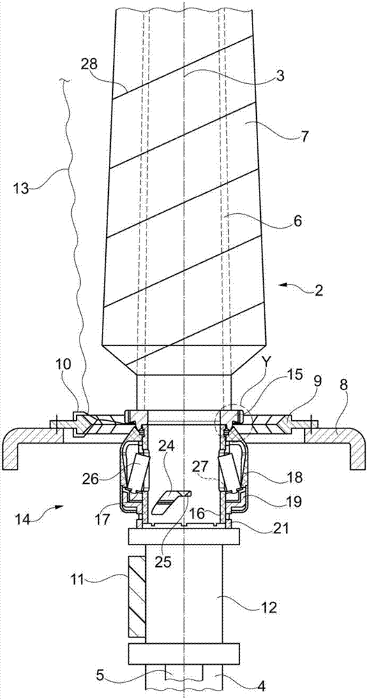
[0079] It is known that many textile machines, especially ring spinning machines or twisting machines, usually have a plurality of identical spinning stations 1 which are arranged at a short distance from one another on the machine longitudinal sides of the textile machine.

[0080] The spinning station 1 of the ring spinning machine shown in the figures has a rotatably mounted driven spindle 2, which is used for the purpose of providing yarn 13 fed by an upstream (not shown) drafting system. Certain yarns are twisted and wound onto spinning bobbins 6 . The spindle 2 of a ring spinning machine or twisting machine is usually driven by a single electric motor or, as in the exemplary embodiment, by means of a rotating drive belt 11 which loads the spindle disk 12 of the spindle 2 (so-called envelope drive) .

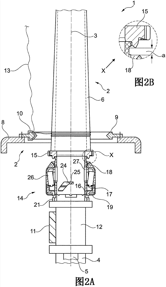
[0081] Such as Figure 1A and Figure 2A As shown, each such spindle 2 has a rotatably mounted upper spindle part 3 and a non-rotating bearing housing 4 which is connecte...


PUM


Abstract

The present invention relates to a thread clamp (14) for a spindle (2) of a spinning or twisting machine, with the spindle top part (3) stationarily arranged first clamping member (15), a relative to the first clamping member (15) axially slidably mounted second clamping element ( 18) and a loading device, the spring force due to the second clamping element (18) acted upon in the direction of the first clamping element (15) and a relief device, the centrifugal force the second clamping member (18) spaced from the first clamping member (15) positioned. According to the invention it is provided that comes as a loading and unloading device comprises a spring element (17) is used, which at a stationarily arranged underwinding sleeve (16) of the spindle (2) is guided and operatively connected to the movably mounted second clamping element (18) is in communication, wherein the spring element (17) is equipped with centrifugal elements (26) that affect, depending on the rotational speed of the spindle (2) the shape of the spring element (17) and thereby set the position of the second clamping element (18).

Description

technical field [0001] The invention relates to a thread clamping device for a spindle of a spinning or twisting machine, comprising: a first clamping element arranged in a fixed manner on the upper spindle part; a second clamping element Element, it is axially displaceably installed with respect to the first clamping element; And loading device, it loads the second clamping element along the direction of first clamping element by means of spring force; And unloading device, it uses centrifugal force to the first clamping element The second clamping element is positioned at a distance from the first clamping element. Background technique [0002] It is known in ring spinning machines that after the bobbins have been produced on at least one machine longitudinal side, first a so-called unwinding has to be carried out, by means of which the relevant machine longitudinal side of the ring spinning machine is ready for the bobbins Subsequent changes to the yarn. [0003] In thi...

Claims


Application Information

Patent Timeline
IPC IPC(8): D01H1/40D01H7/04
CPCD01H1/40D01H7/04B65H65/00B65H2701/31D01H1/38
Inventor G·施陶登迈尔约瑟夫·温特
Owner SAURER COMPONENTS GMBH
Why Eureka
Try Eureka