An elastically actuated dynamic bionic knee joint

An elastic drive and knee joint technology, applied in the fields of biomedical engineering and rehabilitation aids, can solve problems such as being greatly affected by temperature, oil leakage in hydraulic control methods, etc., to reduce muscle energy consumption, improve comfort, and slow down external impacts Effect

Active Publication Date: 2019-04-26
UNIV OF ELECTRONICS SCI & TECH OF CHINA ZHONGSHAN INST +1
View PDF1 Cites 0 Cited by
  • Summary
  • Abstract
  • Description
  • Claims
  • Application Information

AI Technical Summary

Problems solved by technology

Although this patent can also provide active torque for the wearer, the hydraulic control method has problems such as oil leakage and greater influence by temperature.

Method used


Image

  • An elastically actuated dynamic bionic knee joint
  • An elastically actuated dynamic bionic knee joint
  • An elastically actuated dynamic bionic knee joint

Examples


Embodiment Construction

[0020] It should be noted that, in the case of no conflict, the embodiments in the present application and the features in the embodiments can be combined with each other. The present application will be further described in detail below in conjunction with the drawings and specific embodiments.

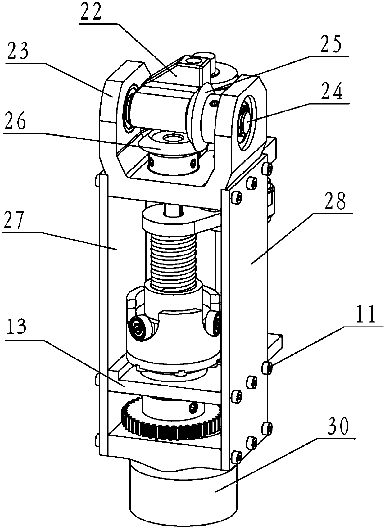
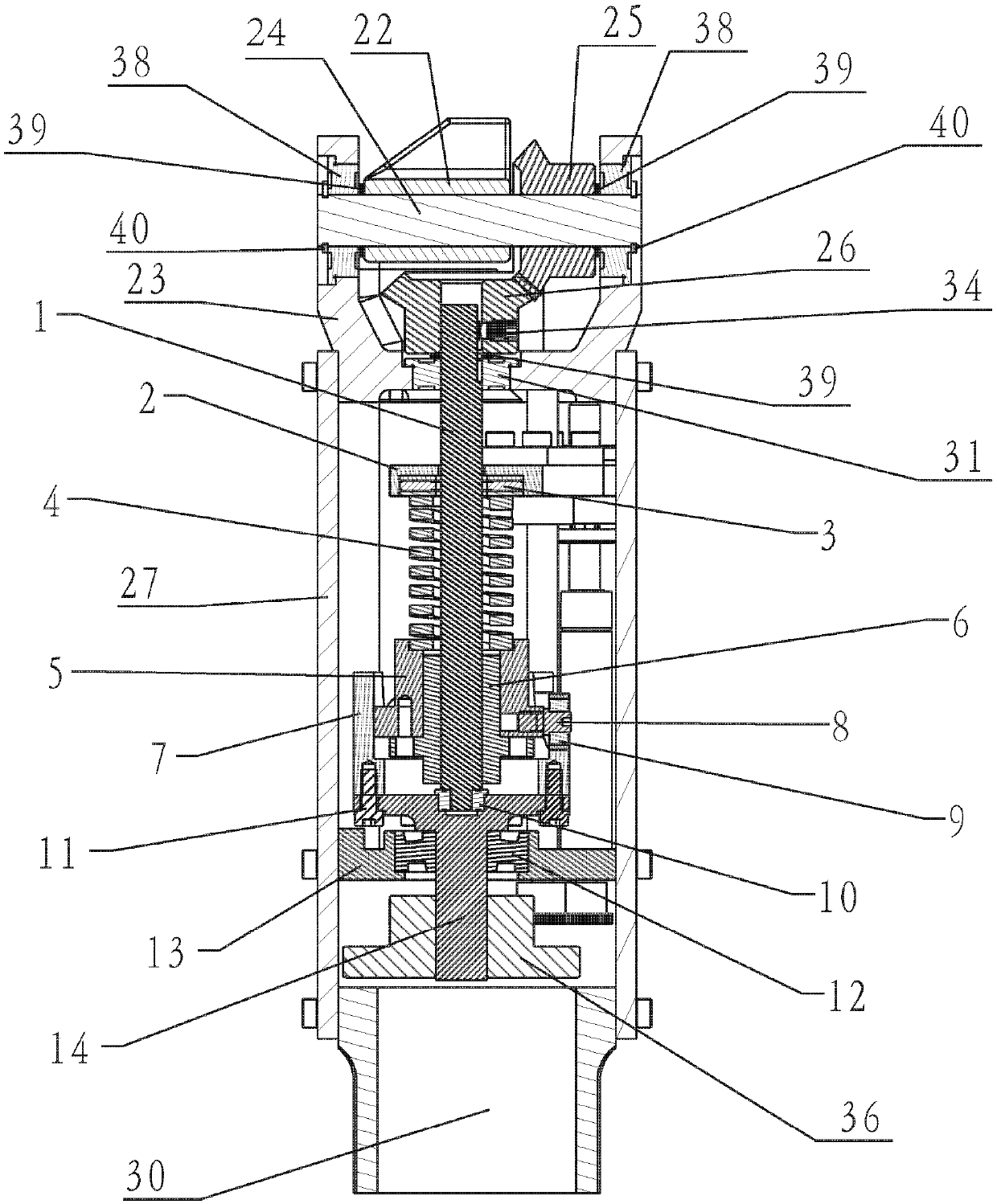
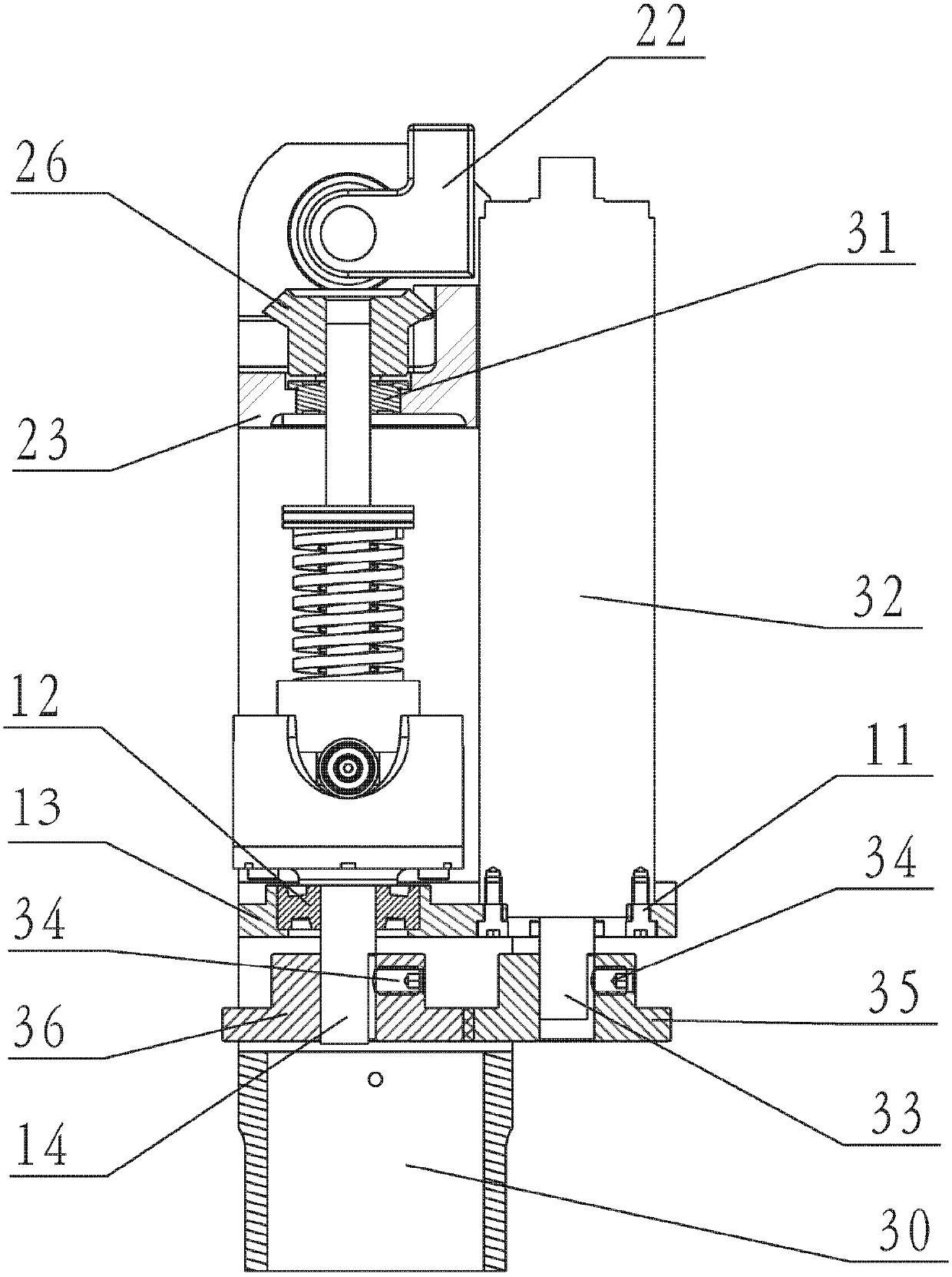
[0021] Such as Figure 1~3 As shown, an elastically driven dynamic bionic knee joint of the present invention includes an active power drive end, a buffer mechanism, a stiffness adjustment mechanism, a knee joint power output end, and a lower leg connection end.

[0022] Such as image 3 As shown, the main driving end includes a main driving motor 32 , a main motor output shaft 33 , a driving spur gear 35 , and a driven spur gear 36 . The main driving motor 32 is integrated with a planetary gear reducer, which is used to provide active power for the bionic knee joint. The main driving motor 32 is fixedly connected to the main motor base 13 by means of locking screws 11 . The outpu...


PUM


Abstract

The invention discloses an elastic-drive dynamic bionic knee joint. The elastic-drive dynamic bionic knee joint comprises an active force driving end, a buffering mechanism, a stiffness adjusting mechanism, a knee joint force output end and a shank connecting end. The active power driving end is used for providing the knee joint active force, the buffering mechanism is connected between the active force driving end and the knee joint force output end and used for conveying the active force of the driving end to the knee joint force output end and comprises an elastic component, and the stiffness adjusting mechanism is connected to the buffering mechanism in a motion mode and changes the precompression amount of the elastic component through facing the buffering mechanism, so that stiffness adjustment of the knee joint is achieved, and the shank connecting end is connected with the knee joint force output end. According to the elastic-drive dynamic bionic knee joint, outer impacts can be effectively slowed down, and the knee joint stiffness is continuously adjustable, so that different motion requirements are met; the active force can be provided for an artificial limb wearer, so that energy consumption of muscles of the patient with an artificial limb is reduced, and the comfort of wearing is improved.

Description

technical field [0001] The invention belongs to the technical field of biomedical engineering and rehabilitation aids, in particular to a dynamic bionic knee joint used in lower limb prosthesis. Background technique [0002] Due to various reasons such as wars, diseases, industrial injuries, traffic accidents and natural disasters, millions of people have lost their healthy lower limbs, and some people have lost their ability to work, which hinders their normal social interactions and bears a huge physical and mental burden. On the other hand, physical disabilities often affect people's daily life, reduce their quality of life, and also bring a heavy burden to their nursing families and society. Since the current level of medical treatment cannot regenerate limbs, installing prosthetic limbs for these amputees has become an important means of compensating for missing limbs. [0003] Existing prosthetic knee joints are mainly passive and semi-active prosthetic knee joints. A...

Claims


Application Information

Patent Timeline
Patent Type & Authority Patents(China)
IPC IPC(8): A61F2/64A61F2/70
CPCA61F2/64A61F2/68
Inventor 彭芳温海阳李智军徐凯赵亭彭威
Owner UNIV OF ELECTRONICS SCI & TECH OF CHINA ZHONGSHAN INST
Why Eureka
Try Eureka