Receiver and assembly technique thereof
A receiver and housing technology, applied in the directions of loudspeakers, sensors, electrical components, etc., can solve the problems of the complex structure of the moving iron unit and the installation process of the receiver, simplify the installation process, ensure the reciprocating vibration, and simplify the electromagnetic drive. Institutional Effects
- Summary
- Abstract
- Description
- Claims
- Application Information
AI Technical Summary
Problems solved by technology
Method used
Image

Examples
Embodiment 1
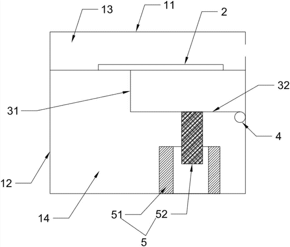
[0065] This embodiment provides a receiver, such as figure 1 As shown, it includes a casing 1 , a diaphragm mechanism 2 , a conductive rod 3 and an electromagnetic drive mechanism 5 .
[0066] Such as figure 1 As shown, the shell 11 includes a first housing 11 composed of a first bottom surface and side walls, and a second housing 12 composed of a second bottom surface and side walls; the open end of the second housing 12 is detachably connected to The opening of the first housing 11 is buckled to form a closed inner cavity.
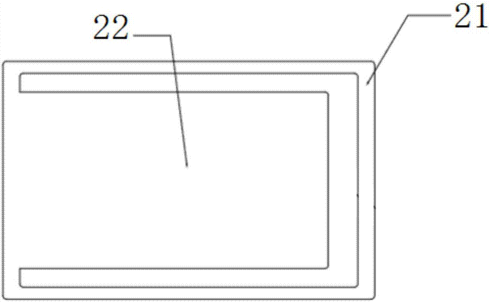
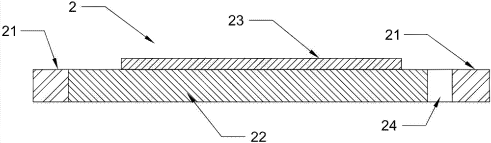
[0067] The diaphragm mechanism 2 is arranged between the openings of the first shell 11 and the second shell 12, and divides the inner cavity of the shell 1 into a first cavity 13 close to the first bottom surface and a second cavity close to the second bottom surface Body 14. That is, the inner cavity of the first housing 11 serves as the first cavity 13 , and the inner cavity of the second housing 12 serves as the second cavity 14 . Both the first ...
Embodiment 2
[0085] This embodiment provides a receiver, which differs from the receiver provided in Embodiment 1 in that the electromagnetic drive mechanism 5 further includes a magnetically permeable housing 53 made of soft magnetic material.
[0086] Such as Figure 4 and Figure 5 As shown, the magnetically permeable housing 53 includes a base 531, an inner cylinder 532 and an outer cylinder 533 arranged in parallel on the base 531 along the direction perpendicular to the installation direction of the vibrating plate 22, and a cover set at a distance between the inner cylinder 532 and the outer cylinder 533. Cover body 534 on the opening that one end of base 531 surrounds; Cover body 534 is an annular cover plate, and the diameter of its annular inner hole can be consistent with the inner hole diameter of inner tube 532, or is less than the inner hole diameter of inner tube 532, only It is necessary to allow the permanent magnet 52 to pass through; the inner cylinder 532, the outer cy...
Embodiment 3
[0095] The difference between the receiver provided in this embodiment and the receiver provided in Embodiment 2 lies in that the number of coils 51 provided in the electromagnetic drive mechanism 5 is different. Such as Figure 6 As shown, there are two coils 51 of the electromagnetic drive mechanism 5 in this embodiment, and the two coils 51 are sleeved on the outer wall of the inner cylinder 532 and located in the closed cavity, and are located at the first end 536 and the second end respectively. at the location where part 537 is located. At the same time, the permanent magnet is fixed on the first connecting part 31, the conduction rod is T-shaped, one end of the horizontal part of the T-shaped part is fixed on the vibrating plate 22, the other end is fixed with a permanent magnet 52, and the other end of the vertical part is fixed on the vibrating plate 22. on the torsion spring. At this time, the second connecting portion 32 acts as a cantilever beam, which can limit ...
PUM
 Abstract
Description
Claims
Application Information
 - R&D
- Intellectual Property
- Life Sciences
- Materials
- Tech Scout
- Unparalleled Data Quality
- Higher Quality Content
- 60% Fewer Hallucinations
Browse by: Latest US Patents, China's latest patents, Technical Efficacy Thesaurus, Application Domain, Technology Topic, Popular Technical Reports.
© 2025 PatSnap. All rights reserved.Legal|Privacy policy|Modern Slavery Act Transparency Statement|Sitemap|About US| Contact US: help@patsnap.com