Method and system for calibrating traffic monitoring model based on physical coordinates of marked dotted line

A traffic monitoring and physical coordinate technology, applied in image data processing, special data processing applications, image analysis, etc., can solve the problems of high hardware cost, large space occupation, and high space occupation rate, achieving strong robustness and easy implementation. Effect

Inactive Publication Date: 2020-04-03
CHANGAN UNIV
View PDF6 Cites 0 Cited by
  • Summary
  • Abstract
  • Description
  • Claims
  • Application Information

AI Technical Summary

Problems solved by technology

In practical applications, it is usually to add additional hardware inside the camera to measure the up and down swing angle of the traffic surveillance camera and the left and right swing angle of the traffic surveillance camera. After adding additional hardware, on the one hand, the cost of the hardware is high and it takes up more space. The cost of each traffic monitoring method is high and the maintenance is troublesome
On the other hand, it is also necessary to consider whether the data transmission is wrong or the frame is dropped, which requires additional verification, which makes it inconvenient to measure the angle through the hardware.
In order to overcome the disadvantages of high cost, high space occupancy and inconvenient measurement caused by the above-mentioned hardware, the present invention proposes a P4P method for camera attitude estimation
[0005] There is no suitable simulation method for the road method to simulate the scene observed by the camera after the traffic video is collected by the existing traffic monitoring method.

Method used


Image

  • Method and system for calibrating traffic monitoring model based on physical coordinates of marked dotted line
  • Method and system for calibrating traffic monitoring model based on physical coordinates of marked dotted line
  • Method and system for calibrating traffic monitoring model based on physical coordinates of marked dotted line

Examples


Embodiment Construction

[0075] The present invention will be described in detail below in conjunction with the drawings:

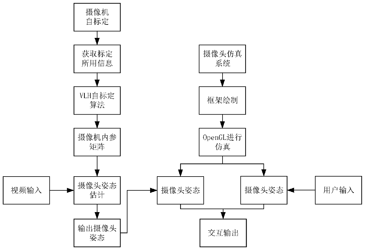
[0076] Such as figure 1 As shown, in order to improve the current situation that there is no suitable simulation method to simulate the change of traffic monitoring cameras after the traffic video is collected, the present invention designs a traffic monitoring model method. Since the common scenes of actual roads include various types of vehicles, solid lines on the road, dashed lines on the road, and traffic cameras beside the road. Therefore, the main function of the model method is to simulate the common scenes of the actual road. The simulation method is written using OpenGL, and the planned design has two other categories besides the interface frame. One of the classes draws vehicles, solid lines, and dashed lines beside various traffic roads; the other class is responsible for displaying the drawn traffic roadside information and receiving user input variables to interact wi...


PUM


Abstract

The invention provides a traffic monitoring model calibration method and system based on physical coordinates of a marking dotted line, and the method comprises the following steps: 1), determining an internal parameter matrix of a road monitoring camera through a VLH self-calibration algorithm; 2), solving the posture parameters of a camera through the internal parameter matrix determined at step 1) and the coordinates of the marking dotted line in a traffic video; 2), obtaining the posture parameters of the camera after the execution of step 2), transmitting the posture parameters to a traffic monitoring model, carrying out the corresponding analysis calculation of the posture of the camera through the traffic monitoring model, and obtaining an accurate road monitoring result. The calculation speed of the traffic monitoring module is higher than the speed of a conventional camera calibration method. The method achieves the real-time calibration, is high in robustness, and is convenient in obtaining based on the coordinates of the marking dotted line. The method can achieve the quick calibration of traffic monitoring facilities through an actual road traffic video, and can achieve the real-time and accurate simulation of traffic video conditions.

Description

Technical field [0001] The invention belongs to the technical field of machine vision of information technology, and relates to a method and system for calibrating a traffic monitoring model based on the physical coordinates of an identification dotted line. Background technique [0002] Due to the improvement of people's manufacturing level, the cost of traditional cameras and processors continues to drop, and vision-based sensors are becoming more popular and gradually replacing traditional sensors to collect traffic data. Many research and commercial companies have declared that they can extract information such as vehicle speed, vehicle capacity, and vehicle type in traffic videos. In addition to cost reduction, the machine vision-based method is easy to install and has abundant data collection capabilities to attract a large number of relevant personnel to conduct research in this area. [0003] In practical applications, the calibration of the camera is mainly focused on the...

Claims


Application Information

Patent Timeline
Patent Type & Authority Patents(China)
IPC IPC(8): G06T7/80G06F30/20
CPCG06F30/20G06T7/80G06T2207/10016G06T2207/30236
Inventor 王伟王崇晓姚镇宇余志成
Owner CHANGAN UNIV
Why Eureka
Try Eureka