
Rotary jaw type air nozzle

A technology of rotating clamps and air nozzles, used in mechanical equipment, couplings, etc., can solve the problems of complex American air nozzles and French air nozzles, the clamping force of complex American air nozzles, the high manufacturing cost of components, and the lack of intuitive operation.

Active Publication Date: 2019-05-14
BETO ENG & MARKETING
View PDF11 Cites 0 Cited by
  • Summary
  • Abstract
  • Description
  • Claims
  • Application Information

AI Technical Summary

Problems solved by technology

[0004] In view of this, the object of the present invention is to provide a rotary jaw type air nozzle to improve the conventional air nozzle joints in the prior art, which have unintuitive operation, many components, high manufacturing cost and complicated assembly operations. And problems such as poor clamping force for American-style valves and French-style valves

Method used


Image

  • Rotary jaw type air nozzle
  • Rotary jaw type air nozzle
  • Rotary jaw type air nozzle

Examples


Embodiment Construction

[0049] In order to enable your review committee to have a further understanding and recognition of the features and features of the present invention, the following preferred embodiments are listed below with accompanying drawings:

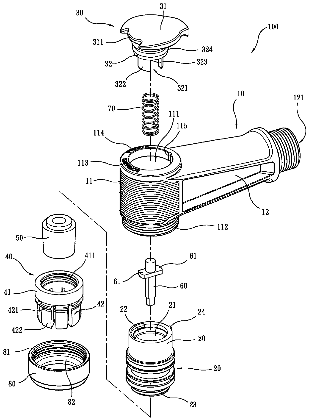
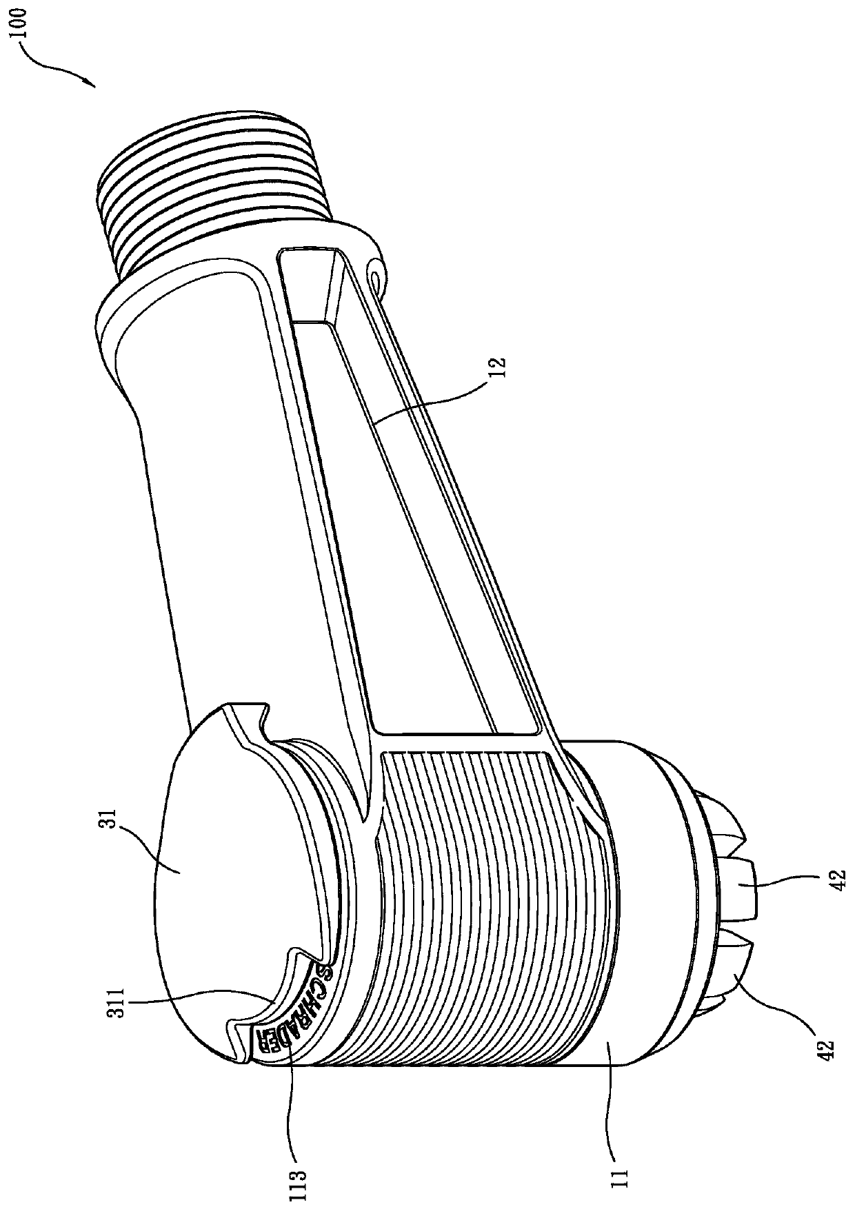
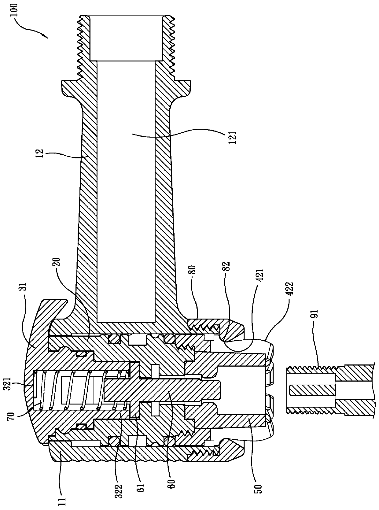
[0050] see Figure 1 to Figure 8 , A rotary jaw type air nozzle 100 provided by a preferred embodiment of the present invention mainly includes an air nozzle body 10, an inner cylinder 20, a screw cap 30, a jaw 40, a beam ring 50, A thimble 60, a spring 70 and an action ring 80, wherein:

[0051] see Figure 1 to Figure 3 , the air nozzle body 10 has an accommodating portion 11 and a connecting portion 12; Screw thread 112, the top of the accommodating portion 11 has an American symbol 113 and a French symbol 114, the connecting portion 12 is integrally connected to one side of the accommodating portion 11, and has an inflatable passage connecting the accommodating chamber 111 to the outside world 121.

[0052] see Figure 1 to Figure 3 , the...


PUM


Abstract

A rotary clamping jaw type valve includes a valve body, an inner cylinder, a rotary cover, a clamping jaw, a bundle ring, an ejector pin, a spring and an action ring. The valve body is provided with a containing chamber with the top and the bottom being through; the inner cylinder is placed in the containing chamber of the valve body and axially provided with an axial hole in a penetrating mode; the rotary cover is rotatably combined with one end of the inner cylinder and located at the top end of the valve body; an indicating area is arranged at one end of the rotary cover, and the other end of the rotating cover is provided with a containing groove extending inwards, two pressing walls and two sliding grooves, wherein the two pressing walls are located on the two opposite sides of the containing groove, and the two sliding grooves are located in the other two opposite sides of the containing groove; a ring part is arranged at one end of the clamping jaw, and a plurality of claw parts are annularly arranged at the other end of the clamping jaw; the bundle ring has the elastic deformation capacity and is placed in the clamping jaw; the ejector pin is placed in the axial hole of the inner cylinder, and two convex wings are arranged on the two opposite sides of the ejector pin; the spring is placed in the containing groove of the rotary cover and abuts against one end of the ejector pin; and the action ring is combined at the bottom end of the valve body, and an annular flange is arranged on the inner peripheral face of the action ring. The rotary clamping jaw type valve is more convenient to operate, low in manufacturing cost, easy to assemble, and capable of promoting the clamping force to an American valve and a French valve.

Description

technical field [0001] The present invention relates to an inflatable device, more specifically, a rotating claw-type air nozzle. Background technique [0002] Press, for different types of tire valves, the known valve joints cannot be used universally, so they must be replaced during use, which is inconvenient to replace. At present, many companies in the industry have developed a valve joint that can be used for American valves and French valves. It mainly designs a lever that can be moved up and down on the outside, and a displaceable thimble on the inside. Pull up and down to drive a number of clamping blocks to clamp, fix and release the thimble, so that when the thimble is pushed inward, the French-style air nozzle can be inflated, and when the thimble is pushed outward, the American-style air nozzle can be inflated. Inflate. [0003] However, the above-mentioned general-purpose air nozzle has some problems in actual use. One is that the lever must be moved up and do...

Claims


Application Information

Patent Timeline
Patent Type & Authority Patents(China)
IPC IPC(8): F16L37/138
CPCF16L37/138
Inventor 王罗平
Owner BETO ENG & MARKETING
Learn More