Diaphragm dividing and cutting machine

A slitter and diaphragm technology, applied in the direction of winding strips, sending objects, thin material processing, etc., can solve problems such as damage to the diaphragm under tension, and achieve the effect of reducing tension and preventing damage

Pending Publication Date: 2017-12-15
深圳市佳得设备科技有限公司
View PDF0 Cites 6 Cited by
  • Summary
  • Abstract
  • Description
  • Claims
  • Application Information

AI Technical Summary

Problems solved by technology

[0003] The purpose of the present invention is to provide a diaphragm slitting machine, aiming to solve the technical problem in the prior art that the diaphragm is damaged due to the high tension of the diaphragm when it is wound by friction

Method used


Image

  • Diaphragm dividing and cutting machine
  • Diaphragm dividing and cutting machine
  • Diaphragm dividing and cutting machine

Examples


Embodiment Construction

[0043] Below in conjunction with specific embodiment and accompanying drawing, the present invention is further elaborated and illustrated:

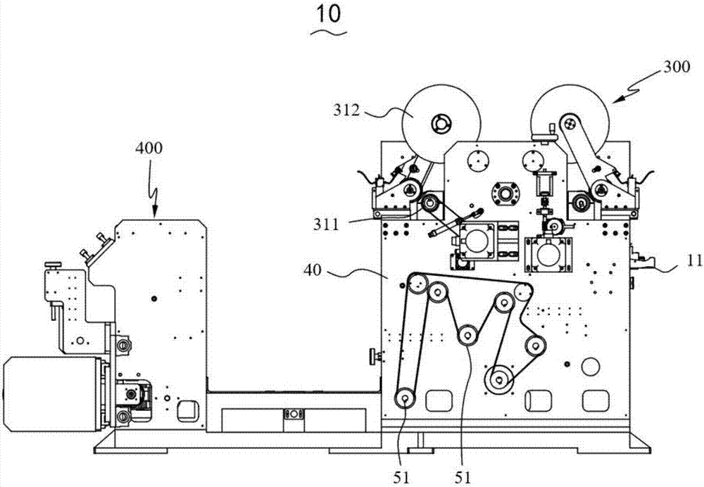
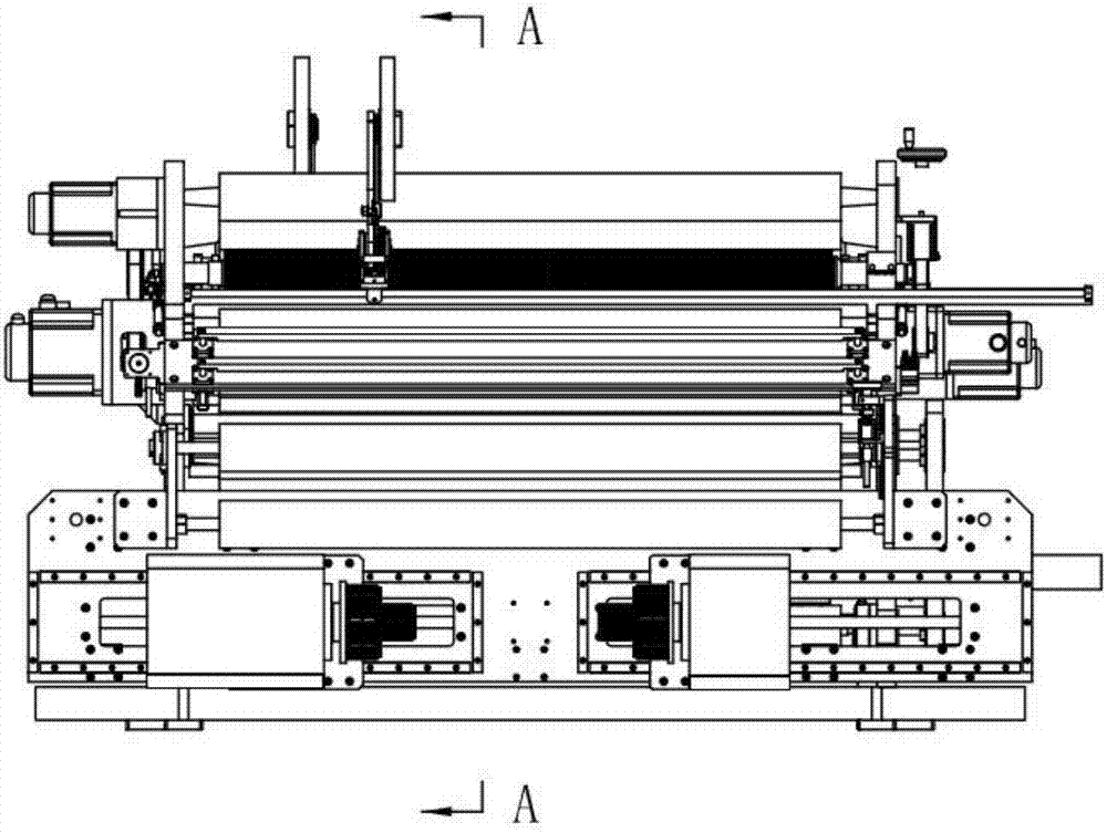
[0044] Please refer to Figure 1 to Figure 7 , the present invention provides a diaphragm slitter 10, the diaphragm slitter 10 includes: a slitting module 100, a separation module 200 and a winding module 300;

[0045] The slitting module 100 receives the diaphragm 20, and cuts the diaphragm 20 so that the diaphragm 20 forms at least two diaphragm belts 21; the separation module 200 is used for actively crimping and conveying the diaphragm 20, and separates the two diaphragm belts 21 for separate output; the winding die The group 300 includes at least two winding devices 31. The winding devices 31 are positioned on the slide rail 30. The two winding devices 31 actively wind up the diaphragm belt 21 respectively. The two winding devices 31 are respectively located on both sides of the separation module 200. The winding device 31 includes...


PUM


Abstract

The invention discloses a diaphragm dividing and cutting machine. The diaphragm dividing and cutting machine comprises a dividing and cutting module, a separating module and a winding module, wherein the dividing and cutting module is used for receiving a diaphragm and cutting the diaphragm so as to to enable the diaphragm to form at least two diaphragm belts, the separating module is used for actively winding and conveying the diaphragm and separating and then outputting the two diaphragm belts separately, the winding module comprises at least two winding devices, the winding devices are located on sliding rails, the sliding rails are arranged parallel to a first transitional roller, the two winding devices actively wind the diaphragm belts separately and are located on the two sides of the separating module separately, and each winding device comprises a slip frequency shaft and a winding box which is driven by the slip frequency shaft to perform rotary winding. Compared with a surface winding mode only through the friction force, the diaphragm dividing and cutting machine has the advantages that the tension on the surface of the diaphragm can be decreased, and the diaphragm can be prevented from being damaged.

Description

technical field [0001] The invention relates to the field of mechanical automation, in particular to a diaphragm cutting machine for cutting a roll diaphragm. Background technique [0002] Most of the existing diaphragm slitting machines are surface winding, that is, relying on friction with the roller body to wind. This winding method is suitable for situations with large thickness changes, large roll diameters, and large tension. Since the diameter of the power roller is constant, it is not affected by the size of the winding diameter, and can always keep the same tension as the unwinding. As long as there is constant friction and counter-pressure tension between the winding stock and the power roll, the winding tension of the winding stock can remain stable. However, the tension on the surface of the rewinding diaphragm is relatively large, which will cause damage to the diaphragm. Contents of the invention [0003] The purpose of the present invention is to provide a...

Claims


Application Information

Patent Timeline
IPC IPC(8): B65H35/02B65H18/10B65H16/06B65H23/26
CPCB65H16/06B65H18/103B65H23/26B65H35/0073B65H35/02B65H2701/19
Inventor 周君
Owner 深圳市佳得设备科技有限公司
Why Eureka
Try Eureka