Eureka AIR delivers breakthrough ideas for toughest innovation challenges, trusted by R&D personnel around the world.

Plastic particle storing tank with distribution device

A technology of diverting device and plastic granules, applied in the direction of conveying bulk materials, packaging, transportation and packaging, etc., can solve the problems of long manual cleaning time, high labor intensity of workers, general cleaning effect, etc., so as to save cleaning work and have a simple structure. , easy to use effect

Active Publication Date: 2017-12-15
DONGGUANG HUI RU LAI POWER TECH CO LTD
View PDF4 Cites 1 Cited by
  • Summary
  • Abstract
  • Description
  • Claims
  • Application Information

AI Technical Summary

Problems solved by technology

The upper end of the storage tank is provided with a material inlet, and the lower end is provided with a material outlet. Both the inlet and the outlet are equipped with flapper valves. The inlet and outlet are controlled by the opening and closing of the flapper valve. Connect with the diversion device, the diversion device diverts the plastic particles, and each material-using mechanism sucks the plastic particles from the diversion device through the suction machine. Most of the existing diversion devices include a diversion main pipe and a plurality of diversion branches connected with the main diversion pipe. Each shunt branch pipe is connected with the suction machine of the material use mechanism. During the use of the existing shunt device, when the flapper valve at the material outlet is closed, the suction machine will continue to work to make the inside of the shunt main pipe become negative pressure. The plastic particles remaining in the diversion main pipe will not be sucked away by the suction machine. When other different types of plastic particles enter the diversion main pipe again, it will cause pollution. Therefore, the current diversion devices are all plug-in plates at the discharge port. When the valve is closed, manually clean the inside of the shunt main pipe. Since the shunt main pipe is located at the bottom of the equipment, almost close to the bottom surface, the manual cleaning time is long, the labor intensity of the workers is high, and the cleaning effect is average.

Method used


Image

  • Plastic particle storing tank with distribution device
  • Plastic particle storing tank with distribution device
  • Plastic particle storing tank with distribution device

Examples


Embodiment Construction

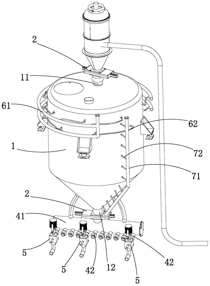
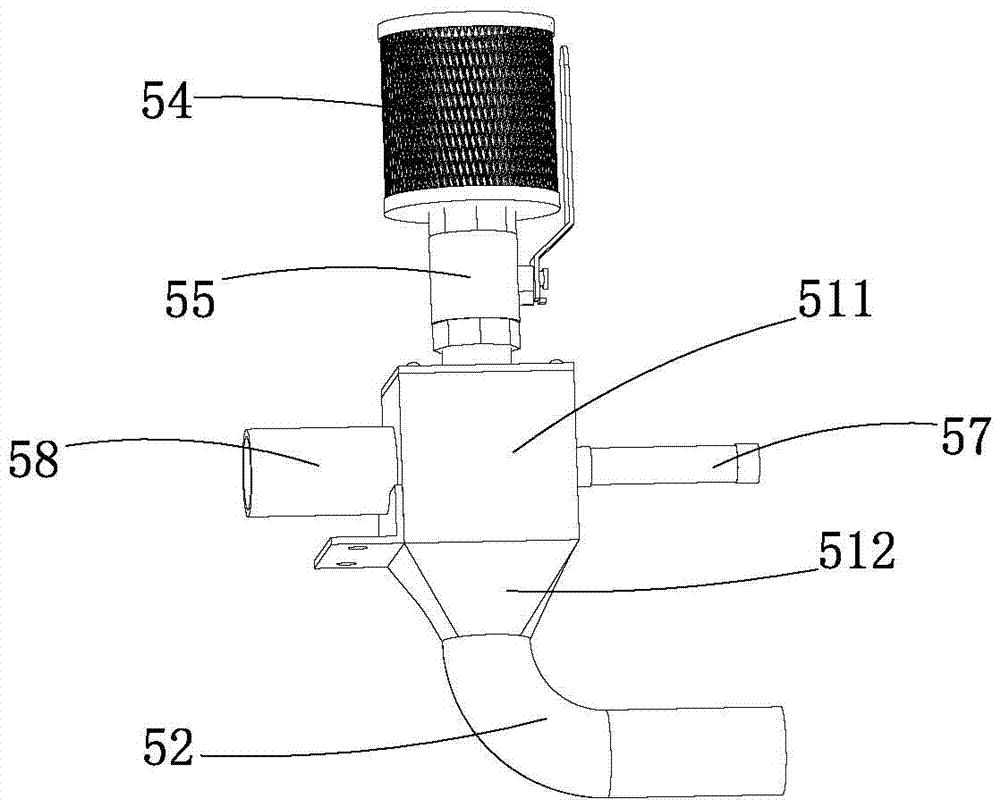
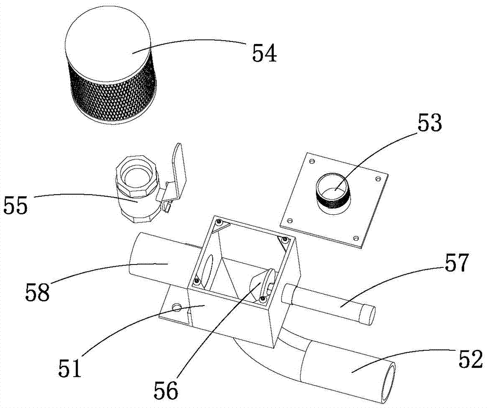
[0025] see Figure 1 to Figure 3 , according to the embodiment of the plastic granule storage tank with a diversion device provided in the present invention, comprising a tank body 1, a cleaning mechanism arranged on the tank body 1 and a diversion device connected to the tank body 1, the tank The body 1 is provided with a feed port 11 and a discharge port 12, and the flow diversion device is connected with the discharge port 12. A plurality of branch branch pipes 42 connected by the main pipe 41, a plurality of branch branch pipes 42 are provided with a material valve 5 with a ventilation channel, and the material valve 5 includes a valve box 51, a valve box located on the side wall of the valve box Feed pipe 58, the discharge pipe 52 that is located at the bottom of the valve box 51, the air inlet 53 that is located at the top of the valve box 51, the valve plug 56 that is located in the valve box 51 and is connected with the valve The handle 57 connected to the plug 56, th...


PUM


Abstract

The invention provides with a plastic particle storing tank with a distribution device. The plastic particle storing tank comprises a tank body, a washing mechanism arranged on the tank body and the distribution device connected with the tank body. The tank body is provided with a feeding port and a discharging port, the distribution device is connected with the discharging port and comprises a distribution main pipe communicating with the discharging port and a plurality of distribution branched pipes communicating with the distribution main pipe, and the multiple distribution branched pipes are provided with material valves with ventilating flow passes correspondingly. The plastic particle storing tank with the distribution device has the beneficial effects that the Venturi effect is generated at the connecting positions of the materials valves and the distribution branched pipes, residual plastic particles in the distribution main pipe are sucked away through the distribution branched pipes, and waste of the residual plastic particles in the distribution main pipe is avoided; meanwhile washing work of the distribution main pipe is omitted, the very convenient effect is achieved in use, the time and labor are saved, and the use cost of the plastic particle storing tank is greatly reduced; and meanwhile the material valves are simple in structure, few in number of component, convenient to assemble and low in production cost.

Description

technical field [0001] The invention relates to a basic equipment of the plastic industry, in particular to a plastic particle storage tank with a diverting device. Background technique [0002] At present, in the production process of the plastics industry, the extruded material strips extruded by the extruder are cooled and dried, pelletized and screened, and then the pellets are sent to the storage tank through the feeder. The upper end of the storage tank is provided with a material inlet, and the lower end is provided with a material outlet. Both the inlet and the outlet are equipped with flapper valves. The inlet and outlet are controlled by the opening and closing of the flapper valve. Connect with the diversion device, the diversion device diverts the plastic particles, and each material-using mechanism sucks the plastic particles from the diversion device through the suction machine. Most of the existing diversion devices include a diversion main pipe and a pluralit...

Claims


Application Information

Patent Timeline
Patent Type & Authority Applications(China)
IPC IPC(8): B65D90/00B65G53/36B65G53/14B65G53/34
CPCB65D90/00B65D90/0093B65G53/14B65G53/34B65G53/36B65G2201/042
Inventor 许纯权
Owner DONGGUANG HUI RU LAI POWER TECH CO LTD
Why Eureka
Eureka Blog
Learn More