
Clamp facilitating both-side welding

A double-sided welding and fixture technology, applied in welding equipment, auxiliary welding equipment, welding/cutting auxiliary equipment, etc., can solve problems such as insufficient welding, affecting welding quality, and affecting welding efficiency, and achieve the effect of ensuring accuracy

Inactive Publication Date: 2017-12-15
贾恒宏
View PDF0 Cites 8 Cited by
  • Summary
  • Abstract
  • Description
  • Claims
  • Application Information

AI Technical Summary

Problems solved by technology

[0002] In the field of processing auto parts, welding processes are often used, such as body panels, which need to be welded. In order to improve the welding efficiency during welding, it is necessary to carry out overall clamp welding. The existing clamps still have the following disadvantages: 1. , The fixture as a whole is more stuck by each limit block, which can avoid the large clamping part and block the position of the solder joint, resulting in insufficient welding and the secondary welding process, but such clamping Unreliable and easy to loosen, which will lead to the deviation of the welding point of the welding size, which will affect the quality of the welding; if the clamping area is increased, some areas will not be welded during welding, and secondary welding will be required, which will affect the quality of the welding. improve the welding efficiency; 2. After one side is welded, the workpiece needs to be disassembled from the fixture, turned over and clamped, so that the subsequent clamping position deviates from the initial clamping position. For the setting of the welding manipulator Welding by the program will cause the solder joints to shift and other conditions, which will affect the quality of welding

Method used


Image

  • Clamp facilitating both-side welding
  • Clamp facilitating both-side welding

Examples


Embodiment Construction

[0019] The present invention will be further illustrated below in conjunction with the accompanying drawings and specific embodiments. This embodiment is implemented on the premise of the technical solution of the present invention. It should be understood that these embodiments are only used to illustrate the present invention and are not intended to limit the scope of the present invention.

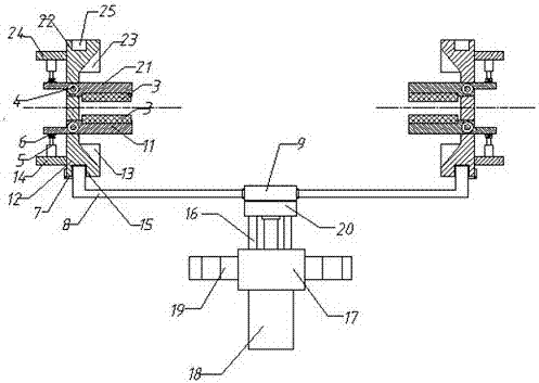
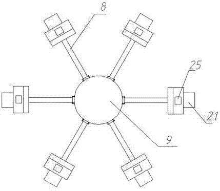
[0020] Such as figure 1 and figure 2 The described fixture for double-sided welding includes a mounting support 19, a guide seat 17, a main connecting block 20 and a moving connecting block 9; the mounting support 19 is fixed on the described guiding seat 17, installed The support 19 is used for fixing the fixture; the guide rod 16 is arranged on the guide seat 17 and is connected with the bottom of the main connecting block 20 through the guide rod 16 .

[0021] The bottom of the guide seat 17 is provided with a lift cylinder 18, the piston rod of the lift cylinder 18 passes through ...


PUM


Abstract

The invention discloses a fixture for double-sided welding, which includes a mounting support, a guide seat, a main connecting block and a moving connecting block. A connecting arm is arranged on the moving connecting block, and a connecting arm is fixed on the connecting arm. Gripper head. The invention can clamp the workpiece well, and the clamping is firm; by connecting the upper splint through the rotating shaft and the cylinder, it can play the role of lifting or pressing the upper splint through the cylinder, and it can be gradually welded during welding. The upper splint is lifted up, and the upper splint is driven down by the cylinder after welding, which can ensure that the clamping is firm, and it can also ensure that the surface of the welded workpiece is completely welded; the lower splint and the upper splint adopt a symmetrical structure, The fixture can be turned over directly for reverse welding without removing the workpiece from the fixture, which can ensure the accuracy of subsequent welding.

Description

technical field [0001] The invention relates to the field of welding, in particular to a clamp for double-sided welding. Background technique [0002] In the field of processing auto parts, welding processes are often used, such as body panels, which need to be welded. In order to improve the welding efficiency during welding, it is necessary to carry out overall clamp welding. The existing clamps still have the following disadvantages: 1. , The fixture as a whole is more stuck by each limit block, which can avoid the large clamping part and block the position of the solder joint, resulting in insufficient welding and the secondary welding process, but such clamping Unreliable and easy to loosen, which will lead to the deviation of the welding point of the welding size, which will affect the quality of the welding; if the clamping area is increased, some areas will not be welded during welding, and secondary welding will be required, which will affect the quality of the weld...

Claims


Application Information

Patent Timeline
IPC IPC(8): B23K37/04B23K37/047
CPCB23K37/0435B23K37/047B23K2101/006
Inventor 贾恒宏
Owner 贾恒宏
Learn More