Machining mold of seat slide rail bracket

A technology for processing molds and slide rails. It is used in forming tools, manufacturing tools, metal processing equipment, etc., and can solve problems such as inability to ensure the size of brackets and the position of holes.

Active Publication Date: 2017-12-15
WUXI WEITANG IND TECH CO LTD
View PDF8 Cites 2 Cited by
  • Summary
  • Abstract
  • Description
  • Claims
  • Application Information

AI Technical Summary

Problems solved by technology

[0003] In view of the above problems, the present invention provides a processing mold for the seat slide rail bracket, which can solve the technical problem that the existing mold cannot ensure the size of the bracket and the position of the hole

Method used


Image

  • Machining mold of seat slide rail bracket
  • Machining mold of seat slide rail bracket
  • Machining mold of seat slide rail bracket

Examples


Embodiment Construction

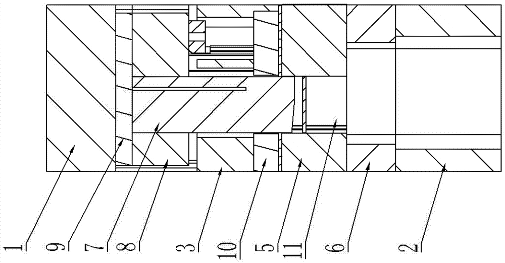
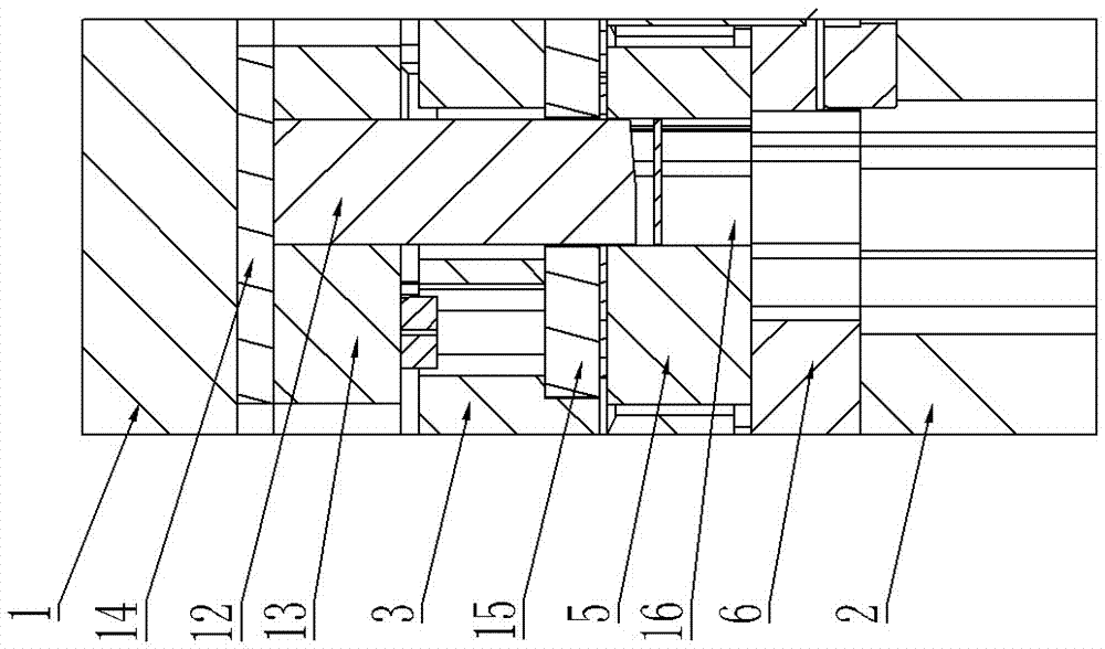
[0034] Such as figure 1 As shown, it includes a shaping device. The shaping device includes a main body shaping mechanism for shaping the main body of the bracket. The shaping device also includes a side shaping mechanism for shaping the bending parts on both sides of the bracket inwardly.

[0035] Figure 7As shown, the processing mold includes an upper mold base 1 and a lower mold base 2, and the upper mold base 1 and the lower mold base 2 are guided to mold by a guide mechanism, and a stripper plate 3 is installed under the upper mold base 1; the main body shaping mechanism includes a plastic upper Module 31 and shaping lower module 34, the shaping upper module 31 is fixed under the stripper plate 3, the shaping lower module 34 is fixed on the lower mold base 2; the side shaping mechanism is provided with two groups, which are respectively arranged on both sides of the main body shaping mechanism (due to the support processing in pairs, so the side shaping mechanism is al...


PUM


Abstract

The invention provides a machining mold of a seat slide rail bracket capable of solving the technical problem that a traditional mold cannot guarantee the bracket size and the hole position degree. The machining mold comprises a shaping device; and the shaping device comprises a main body shaping mechanism for shaping a main body of a bracket. The machining mold is characterized in that the shaping device further comprises a side shaping mechanism for inwards shaping the side part of the bracket.

Description

technical field [0001] The invention relates to the technical field of molds, in particular to a processing mold for a seat slide rail bracket. Background technique [0002] A stent with a structure such as Figure 11 As shown, the side part and the top part are connected through the bending part, because the bracket is generally processed in pairs, that is, it is formed before cutting as Figure 12 As shown in the bow-shaped structure, the structure tends to spring back to the outside, which not only causes the size of the bracket to fail to meet the requirements, but also causes the position of the holes on the side of the bracket to fail to meet the requirements. Contents of the invention [0003] In view of the above problems, the present invention provides a processing mold for the seat slide rail bracket, which can solve the technical problem that the existing mold cannot ensure the size of the bracket and the position of the hole. [0004] The technical solution is...

Claims


Application Information

Patent Timeline
Patent Type & Authority Applications(China)
IPC IPC(8): B21D37/10B21D37/12
CPCB21D37/10B21D37/12Y02P70/10
Inventor 龚静江宁国万
Owner WUXI WEITANG IND TECH CO LTD
Why Eureka
Try Eureka