Display control method, feedback circuit, display device and IC (integrated circuit)
A display control method and display device technology, applied in the fields of display control method, feedback circuit, display device and IC circuit, capable of solving problems such as horizontal stripes on display panels
- Summary
- Abstract
- Description
- Claims
- Application Information
AI Technical Summary
Problems solved by technology
Method used
Image
Examples
Embodiment 1
[0035] A display control method provided by an embodiment of the present invention is introduced in detail.
[0036] The display device includes a plurality of pixel units arranged in an array and common electrodes 102, 104, 106 connected to corresponding row pixel units 101, 103, 105, see figure 1 The display device shown.
[0037] In this embodiment, the voltage on a row of pixel units 101 is affected by the common electrode 102. Since the voltage value of the common electrode 102 is different in display mode and touch mode, the voltage applied to a row of pixel units 101 will fluctuate. As a result, the display brightness of the pixel unit 101 is different when the display mode and the touch mode are switched. If the voltages of the common electrodes 102 and 104 in two adjacent rows are different, the display brightness of the pixel units 101 and 103 in the two adjacent rows will be different, and horizontal stripes will be generated.
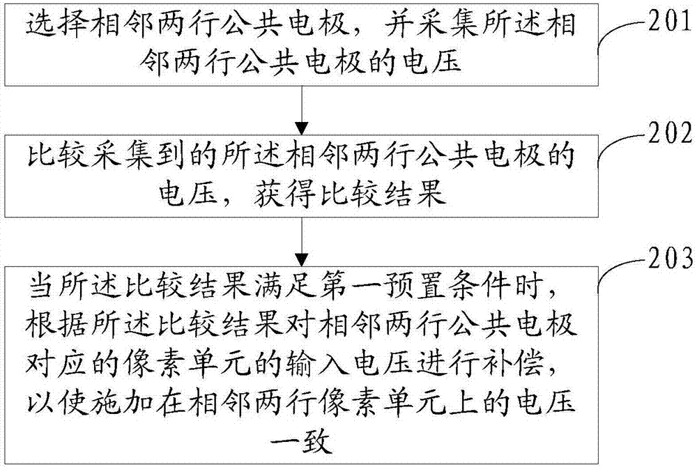
[0038] refer to figure 2 , which ...
Embodiment 2
[0051] refer to Figure 4 , shows a feedback circuit provided by an embodiment of the present invention, which is applied to a display device, and the display device includes a plurality of pixel units arranged in an array and common electrodes 102, 104 correspondingly connected to the pixel units 101, 103, 105 in each row , 106, see figure 1 .
[0052] The feedback circuit 30 includes an acquisition module 301, a comparison module 302 and a compensation module 303 connected in sequence, the other end of the acquisition module 301 is connected to the common electrodes 102, 104, 106, and the other end of the compensation module 303 is connected to the The pixel units 101, 103, 105 are connected;
[0053] The collection module 301 is configured to select two adjacent rows of common electrodes, and collect the voltages of the two adjacent rows of common electrodes;
[0054] The comparison module 302 is configured to compare the collected voltages of the two adjacent rows of co...
Embodiment 3
[0066] A display device provided by an embodiment of the present invention is introduced in detail. The display device includes a plurality of pixel units arranged in an array and a common electrode correspondingly connected to each row of pixel units, and the other end of the pixel unit and the common electrode is connected to both ends of the above-mentioned feedback circuit;
[0067] The pixel unit displays according to the compensation voltage input by the feedback circuit.
[0068] In this embodiment, the feedback circuit 30 includes an acquisition module 301 , a comparison module 302 and a compensation module 303 connected in sequence. The common electrode in the display device is connected to the acquisition module 301 in the feedback circuit 30 , and the pixel units in the display device are connected to the compensation module in the feedback circuit 30 . The feedback circuit 30 collects and compares the voltages of two adjacent rows of common electrodes in the displ...
PUM
 Abstract
Description
Claims
Application Information
 - R&D Engineer
- R&D Manager
- IP Professional
- Industry Leading Data Capabilities
- Powerful AI technology
- Patent DNA Extraction
Browse by: Latest US Patents, China's latest patents, Technical Efficacy Thesaurus, Application Domain, Technology Topic, Popular Technical Reports.
© 2024 PatSnap. All rights reserved.Legal|Privacy policy|Modern Slavery Act Transparency Statement|Sitemap|About US| Contact US: help@patsnap.com


