
An ultrahigh frequency partial discharge detection system calibration method

A technology of partial discharge detection and calibration method, applied in the direction of measuring devices, measuring electrical variables, instruments, etc., can solve problems such as unfavorable selection and purchase of operating units, missed reports of sensors and UHF partial discharge detection devices, and investment waste. , to achieve the effect of promoting the healthy and orderly development of the industry, promoting the safe and stable operation of the power grid, and reducing the interference of the external environment

Inactive Publication Date: 2017-12-12
ELECTRIC POWER RES INST OF GUANGXI POWER GRID CO LTD
View PDF5 Cites 8 Cited by
  • Summary
  • Abstract
  • Description
  • Claims
  • Application Information

AI Technical Summary

Problems solved by technology

However, the construction of technical standards and specifications related to partial discharge ultra-high frequency (UHF) detection lags behind. So far, no consistent and effective evaluation method has been formed internationally, and this aspect is still in a blank stage in China.
Due to the lack of uniform standards and scientific and effective means in the industry to quantitatively evaluate the performance of UHF sensors and UHF partial discharge detection devices, the product level is uneven, which is not conducive to the selection and procurement of operating units, and cannot effectively guarantee network access detection equipment quality level
Engineering practice has found that a large number of UHF sensors and UHF partial discharge detection devices that have been installed have false alarms and false alarms, which not only cause waste of investment, but also cause very bad effects, seriously hindering the promotion and application of UHF partial discharge technology and Affects the effectiveness of condition-based maintenance work

Method used


Image

  • An ultrahigh frequency partial discharge detection system calibration method
  • An ultrahigh frequency partial discharge detection system calibration method
  • An ultrahigh frequency partial discharge detection system calibration method

Examples


Embodiment Construction

[0033] In order to better understand the present invention, the following further describes the present invention with reference to the accompanying drawings and specific embodiments:

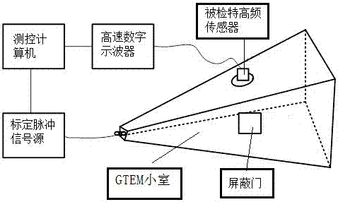
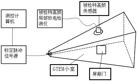
[0034] Such as figure 1 with figure 2 As shown, a device used in a calibration method of a UHF partial discharge detection system includes a calibration pulse signal source, a GTEM cell, a unipolar standard probe, a high-speed digital oscilloscope, and a measurement and control computer; the UHF partial discharge detection system Including the tested UHF sensor, the tested UHF partial discharge detector; this method detects the UHF sensor’s frequency domain equivalent height, detects the sensitivity of the UHF PD detection system, and detects the UHF The dynamic range of the partial discharge detection system is to calibrate the UHF partial discharge detection system. The specific method is as follows:

[0035] (1) Detect the frequency domain equivalent height of the tested UHF sensor

[0036] 1) T...


PUM

PropertyMeasurementUnit
Heightaaaaaaaaaa
Diameteraaaaaaaaaa

Abstract

The invention relates to the technical field of partial discharge detection and in particular provides an ultrahigh frequency partial discharge detection system calibration method. Devices used by the method include a pulse signal source, a GTEM cell, a single-pole standard probe, a high speed digital oscilloscope and a measurement and control computer. The method calibrates an ultrahigh frequency partial discharge detection system by detecting the frequency domain equivalent height of a detected ultrahigh frequency sensor, the sensitivity of the ultrahigh frequency partial discharge detection system and the dynamic range of the ultrahigh frequency partial discharge detection system; detection results are expressed as a unified dimension, and the physical nature of detected objects is reflected; the method takes into full consideration the installing structure of the ultrahigh frequency sensor for detection thereof and fully reflects the engineering practice detection capability thereof; when being used for detection of the ultrahigh frequency partial discharge detection system, the method has the advantages of high shield effectiveness, stable testing results and less influence from external environment disturbance.

Description

Technical field [0001] The invention relates to the technical field of partial discharge detection, in particular to a calibration method of a UHF partial discharge detection system. Background technique [0002] Partial discharge ultra-high frequency online detection is a recognized high-sensitivity and high-efficiency detection technology for discovering potential insulation defects of high-voltage power equipment. With the deepening of the state maintenance of the power system in our country, the application of partial discharge ultra-high frequency (UHF) detection technology in high-voltage electrical equipment (GIS, cables, power transformers, etc.) is becoming more and more extensive. Especially for GIS, this technology has become the most important online monitoring method, and at this stage it has entered the stage of large-scale promotion and application across the country. However, the construction of relevant technical standards and specifications for partial discharg...

Claims


Application Information

Patent Timeline
IPC IPC(8): G01R35/00
CPCG01R35/007
Inventor 吴秋莉黎大健张玉波陈梁远张磊蒲金雨苏星华颜海俊余长厅
Owner ELECTRIC POWER RES INST OF GUANGXI POWER GRID CO LTD
Learn More