
Method and device for measuring longitudinal displacement of steel rail

A longitudinal displacement, rail technology, applied in measuring devices, optical devices, instruments, etc., can solve problems such as poor vibration resistance and low data accuracy

Pending Publication Date: 2017-12-12
RAILWAY ENG RES INST CHINA ACADEMY OF RAILWAY SCI +4
View PDF6 Cites 4 Cited by
  • Summary
  • Abstract
  • Description
  • Claims
  • Application Information

AI Technical Summary

Problems solved by technology

[0006] The embodiment of the present invention provides a method and device for measuring the longitudinal displacement of the rail, so as to at least solve the technical problem in the related art that the device for detecting the displacement of the rail has poor vibration resistance and the accuracy of the detected data is low.

Method used


Image

  • Method and device for measuring longitudinal displacement of steel rail
  • Method and device for measuring longitudinal displacement of steel rail
  • Method and device for measuring longitudinal displacement of steel rail

Examples


Embodiment 1

[0017] According to an embodiment of the present invention, an embodiment of a method for measuring the longitudinal displacement of a rail is provided. It should be noted that the steps shown in the flowchart of the accompanying drawings can be executed in a computer system such as a set of computer executable instructions, Also, although a logical sequence is shown in the flowchart, in some cases, the steps shown or described may be performed in a different order than here.

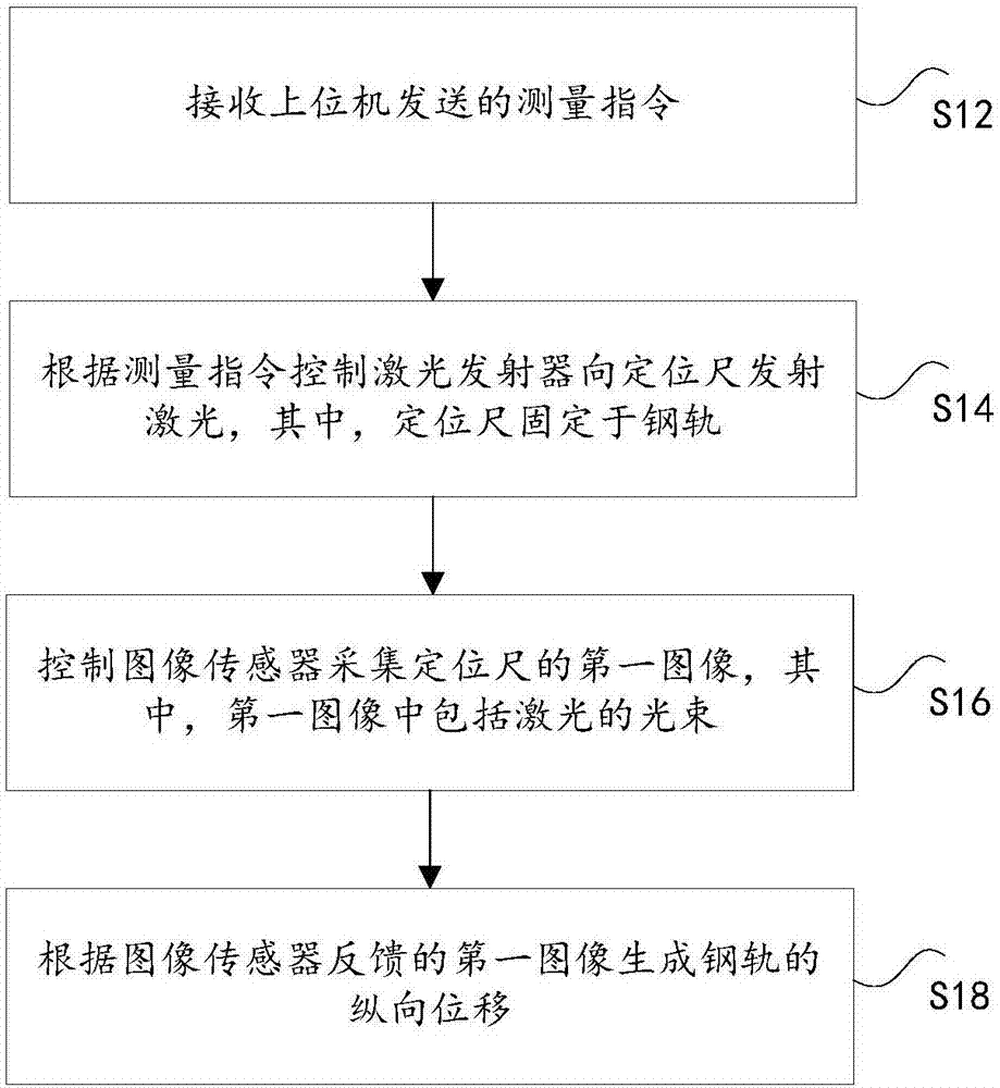
[0018] figure 1 It is a flowchart of a method for measuring the longitudinal displacement of a rail according to an embodiment of the present invention, such as figure 1 As shown, the method includes the following steps:

[0019] Step S12, receiving the measurement instruction sent by the upper computer.

[0020] Specifically, in this solution, the measurement sensor device can be used to establish a communication relationship with the host computer, and the host computer can send a measurement instruction to ...

Embodiment 2

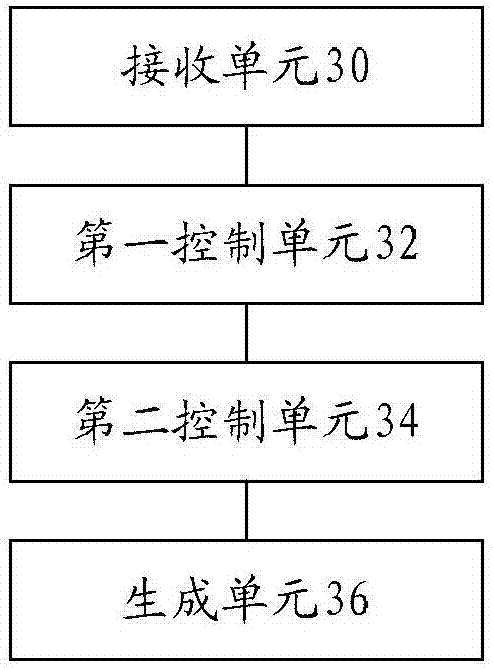
[0045] This application also provides a device for measuring the longitudinal displacement of a rail, such as image 3 As shown, the device may include: a receiving unit 30 for receiving measurement instructions sent by a host computer; a first control unit 32 for controlling the laser transmitter to emit laser light to the positioning ruler according to the measurement instruction, wherein the positioning ruler is fixed on the rail The second control unit 34 is used to control the image sensor to collect the first image of the positioning ruler, wherein the image includes the laser beam; the generation unit 36 ​​is used to generate the longitudinal displacement of the rail according to the first image fed back by the image sensor.

[0046] In this embodiment, the measurement instruction sent by the host computer is received; the laser transmitter is controlled to emit laser light to the positioning ruler according to the measurement instruction, wherein the positioning ruler is f...


PUM


Abstract

The invention discloses a method and device for measuring longitudinal displacement of a steel rail. The method comprises: a measurement instruction sent by the upper computer is received; according to the measurement instruction, a laser transmitter is controlled to emit laser to a positioning gauge fixed at a steel rail; an image sensor is controlled to collect a first image of the positioning gauge, wherein the first image includes a laser beam; and according to the first image fed back by the image sensor, longitudinal displacement of the steel rail is generated. Therefore, a technical problem of low detected data precision caused by the poor anti-vibration performance of the apparatus for detecting the displacement of the steel rail according to the correlated technique is solved.

Description

Technical field [0001] The invention relates to the railway field, and in particular to a method and device for measuring the longitudinal displacement of a steel rail. Background technique [0002] When laying a new seamless railway, it is necessary to lock the rail only when the track is stretched uniformly and the track temperature meets the locked rail temperature range. In order to monitor whether the track is stretched evenly at any time, it is often necessary to set the track at 1000 or 1500 meters. Monitor the stretching of each point of the track within the scope. [0003] In the prior art, magnetic ruler detection technology and rope distance measurement technology are often used to measure the displacement of the steel rail. In the magnetic ruler detection technology, a magnetic displacement reading device is used to obtain the rail displacement data. In the technology, one end of the rope displacement sensor is fixed on the rail, and one section is fixed on the track p...

Claims


Application Information

Patent Timeline
IPC IPC(8): G01B11/02
CPCG01B11/02
Inventor 杜香刚赵勇蔡德钩王继军肖俊恒蒋金洲梁晨徐玉坡徐宏超王彦文吴鑫贺宇
Owner RAILWAY ENG RES INST CHINA ACADEMY OF RAILWAY SCI
Learn More