


Quick Research
Generate reliable direction feasibility study reports for your R&D in just a few steps.

Technical Q&A
Discover and master advanced knowledge NOW. Basics, ideas, possibilities, all at once.

Find Solutions
As an expert in R&D theories, this can generate solutions to your technical problems instantly.

Evaluate Feasibility
Analyze your overall solution with one click, know your potential R&D risks in advance.

Monitor Landscape
Get weekly tech updates, stay abreast of the latest tech innovations and key insights.
Sludge drying and reducing device and method
A sludge drying and reduction technology, applied in chemical instruments and methods, sludge treatment, water/sludge/sewage treatment, etc. Scraping and other problems, to achieve the effect of good sealing, low thermal energy consumption, and preventing air from entering
- Summary
- Abstract
- Description
- Claims
- Application Information
AI Technical Summary
Problems solved by technology
Method used
Image

Examples
Embodiment 1
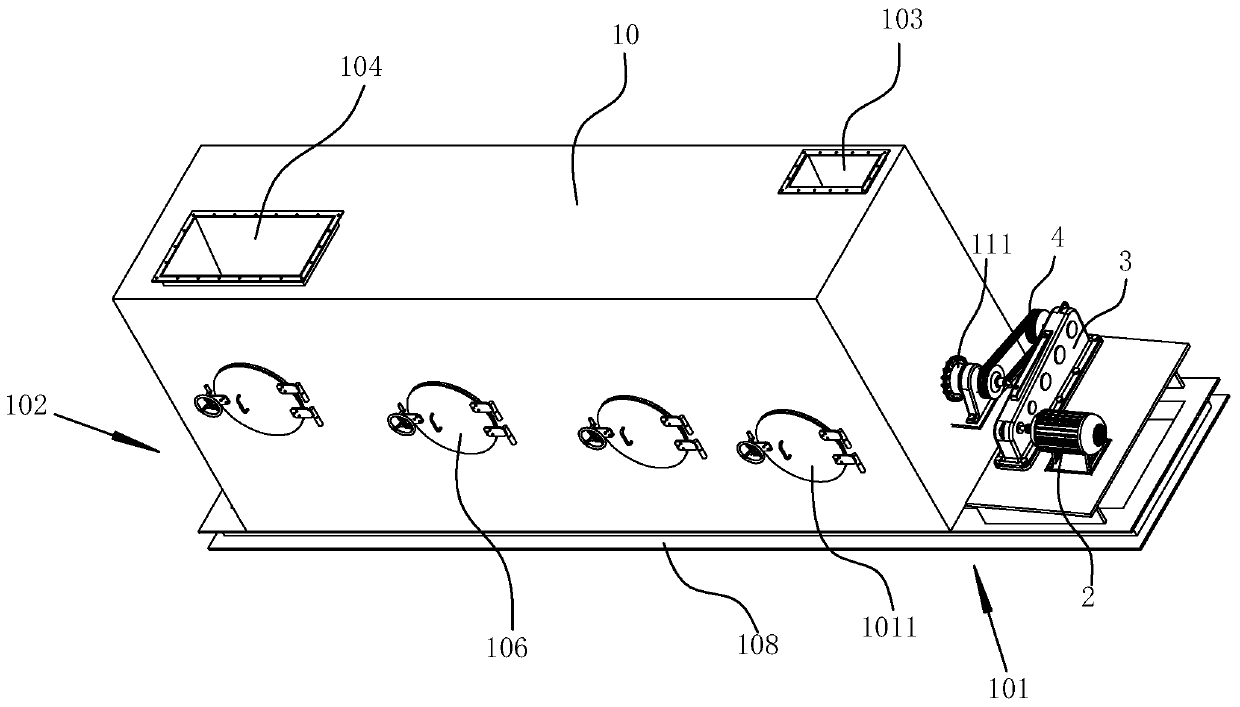
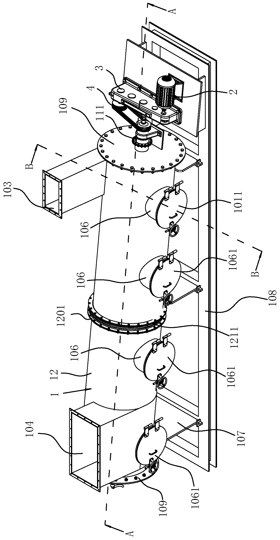
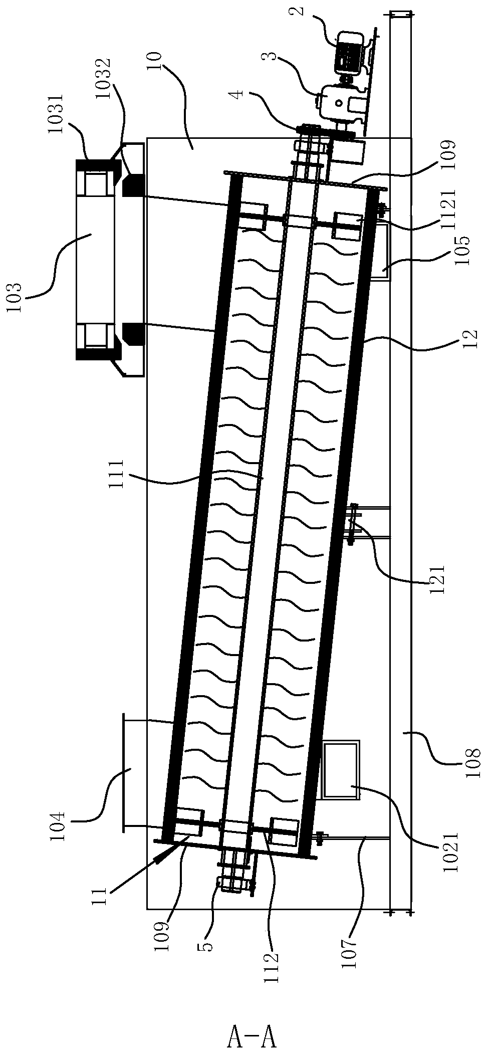
[0040] Figure 1 to Figure 4 It schematically shows a sludge drying and reducing device provided according to the first embodiment of the present invention.
[0041] Such as Figure 1 to Figure 3 As shown, the sludge drying and reducing device disclosed in the present invention includes a horizontally arranged hollow cylindrical drying cylinder 1, and the two ends of the drying cylinder 1 are sealed by the second flange 109, in order to improve the connection between the second flange 109 and the drying cylinder 1. To ensure the tightness between them, a sealing strip structure (not shown in the figure) is provided at the joint of the second flange 109 . The drying cylinder 1 comprises a feed end 101 and a discharge end 102 positioned at two ends of the drying cylinder 1, such as figure 1 As shown, its feed port 101 is provided with a feed port 1011, and the feed port 1011 is located on the side of the drying cylinder 1 cylinder body, and its position takes into account the co...
Embodiment 2
[0053] A sludge drying and reducing device disclosed in Example 2 of the present invention is basically the same as in Example 1, the difference is that:
[0054] In this embodiment of the present invention, the blades 1122 of the material propulsion unit 11 form an included angle of 30° with the radial plane of the rotating shaft 111, and all the blades 1122 are in the same direction; the total length of the drying cylinder 1 is 5 m.
[0055] A kind of sludge drying reduction method disclosed in Example 2 of the present invention is also basically the same as in Example 1, the difference is:
[0056] Step S2: Pass the flue gas at 850°C generated by the sludge incinerator through the air inlet 103 of the drying cylinder 1, while controlling the flue gas feeding speed at 3m / s.
[0057] In the sludge drying and reducing device and method disclosed in this embodiment of the present invention, the 850°C high-temperature flue gas generated by the sludge incinerator passes through t...
Embodiment 3
[0059] A kind of sludge drying and reducing device disclosed in embodiment 3 of the present invention is basically the same as in embodiment 1, the difference is:
[0060] In this embodiment of the present invention, the blades 1122 of the material propulsion unit 11 form an included angle of 60° with the radial plane of the rotating shaft 111, and all the blades 1122 are in the same direction; the total length of the drying cylinder 1 is 4m.
[0061]A kind of sludge drying reduction method disclosed in Example 2 of the present invention is also basically the same as in Example 1, the difference is:
[0062] Step S2: Pass the flue gas at 950°C generated by the sludge incinerator through the air inlet 103 of the drying cylinder 1, while controlling the flue gas feeding speed at 12m / s.
[0063] In the sludge drying and reducing device and method disclosed in this embodiment of the present invention, the 950°C high-temperature flue gas generated by the sludge incinerator passes t...
PUM
| Property | Measurement | Unit |
|---|---|---|
| length | aaaaa | aaaaa |
| length | aaaaa | aaaaa |
| length | aaaaa | aaaaa |
Abstract
Description
Claims
Application Information
 - R&D Engineer
- R&D Manager
- IP Professional
- Industry Leading Data Capabilities
- Powerful AI technology
- Patent DNA Extraction
Browse by: Latest US Patents, China's latest patents, Technical Efficacy Thesaurus, Application Domain, Technology Topic, Popular Technical Reports.
© 2024 PatSnap. All rights reserved.Legal|Privacy policy|Modern Slavery Act Transparency Statement|Sitemap|About US| Contact US: help@patsnap.com