
Multifunctional pill distribution equipment

A dispensing equipment and multi-functional technology, applied in the field of multi-functional pill dispensing equipment, can solve the problems of high cost, complex equipment structure, inaccurate bottling weight, etc., and achieve the effects of controllable weight, convenient operation and simple operation

Inactive Publication Date: 2017-12-12
YANCHENG XINANZHOU PHARMA
View PDF0 Cites 3 Cited by
  • Summary
  • Abstract
  • Description
  • Claims
  • Application Information

AI Technical Summary

Problems solved by technology

[0002] In the continuous production line of pills, due to the different processing time of each process, it is usually necessary to distribute the pills from one equipment to multiple equipments in the next process at the same time to perform different processing, bottling and other processes on the pills to improve the quality of the pills. In addition, the pills processed in the previous process usually need to be lifted from a low place to a certain height to facilitate processing in the next process. Most of the pill lifting and conveying equipment in the prior art uses a motor-driven inclined conveyor belt, but This kind of conveying equipment continuously conveys pills and does not have the function of pill distribution. In the pill production line, the pills move intermittently, because the pills need to stay for a considerable time in many processing procedures, so the conveying process of the pills There is a certain time interval. When distributing and bottling, it is generally calculated by weight. However, due to the different production intervals of pills, the frequency of bottling equipment and distributing equipment is not uniform, resulting in inaccurate bottling weight, and the existing The equipment structure is complex, the cost is high, a large number of equipment drivers are required, and high-precision weighing instruments are required to support the work

Method used


Image

  • Multifunctional pill distribution equipment
  • Multifunctional pill distribution equipment

Examples


Embodiment Construction

[0015] The following will clearly and completely describe the technical solutions in the embodiments of the present invention with reference to the accompanying drawings in the embodiments of the present invention. Obviously, the described embodiments are only some, not all, embodiments of the present invention.

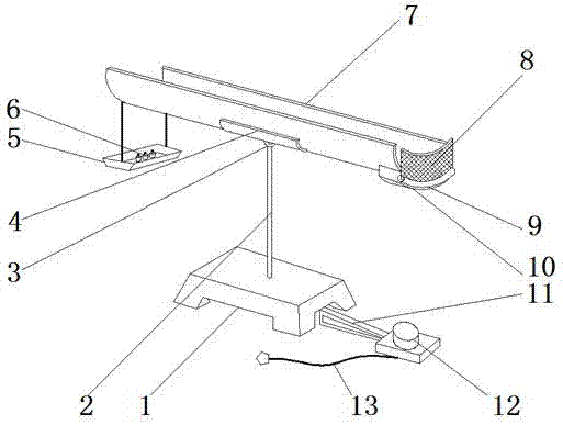
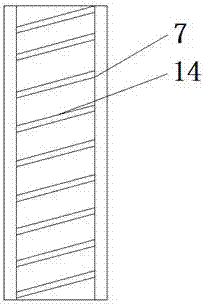
[0016] refer to figure 1 and figure 2 , a multifunctional pill dispensing device, comprising a weight plate 5 and a counterweight base 1 fixed on the ground, a weight 6 is placed on the top inner wall of the weight plate 5, and a first through holes, and the inner wall of the first through hole is plugged with a support rod 2, the outer wall of the top of the support rod 2 is welded with a ferrule, and the inner wall of the ferrule is clamped with a rotary hinge 3, and the outer wall of the top of the ferrule is welded with a supporting plate 4, and the supporting plate 4 The outer wall of the top is clamped with a slideway 7, and there are second through holes on ...


PUM


Abstract

The invention discloses a multifunctional pill dispensing device, which comprises a weight plate and a counterweight base fixed on the ground. Weights are placed on the inner wall of the top of the weight plate, and a hole is opened on the central axis of the outer wall of the top of the counterweight base. a first through hole, and a strut is inserted into the inner wall of the first through hole, a ferrule is welded on the outer wall of the top of the strut, and a rotary hinge is clamped on the inner wall of the ferrule, and a supporting plate is welded on the outer wall of the ferrule top, and A slideway is clamped on the outer wall of the top of the supporting plate, and second through holes are opened on both sides of the outer wall on one side of the slideway. The present invention simulates the whole device as a balance through slideways, brackets and counterweight bases. The operation is simple, and the weight is controllable. The accuracy of the weights will directly affect the accuracy of the weight of the pills. The slideway swings back and forth, the pills flow back to the other side of the slideway, and the electric hinge will automatically turn over when it reaches a certain weight, which makes the operation more convenient and will not cause the weight to fail to meet the standard.

Description

technical field [0001] The invention relates to the technical field of dispensing equipment, in particular to a multifunctional pill dispensing equipment. Background technique [0002] In the continuous production line of pills, due to the different processing time of each process, it is usually necessary to distribute the pills from one device to multiple devices in the next process, and simultaneously perform different processing and bottling of the pills to improve the quality of the pills. In addition, the pills processed in the previous process usually need to be lifted from a low place to a certain height to facilitate processing in the next process. Most of the pill lifting and conveying equipment in the prior art uses a motor-driven inclined conveyor belt, but This kind of conveying equipment continuously conveys pills and does not have the function of distributing pills. In the pill flow production line, the pills move intermittently, because the pills need to stay ...

Claims


Application Information

Patent Timeline
IPC IPC(8): B65B1/32
CPCB65B1/32
Inventor 陈诚乐
Owner YANCHENG XINANZHOU PHARMA
Learn More