
Cam-controlled follow-up pressure roller mechanism

A pressure roller mechanism and cam control technology, applied in printing machines, general parts of printing machinery, printing, etc., can solve the problems of not being able to meet the requirements of high-precision printing product inspection, difficult to control friction, and out-of-control paper movement, etc., to achieve Ensure the effect of stability, convenient operation and strong versatility

Inactive Publication Date: 2017-12-12
江苏昌昇集团股份有限公司
View PDF0 Cites 0 Cited by
  • Summary
  • Abstract
  • Description
  • Claims
  • Application Information

AI Technical Summary

Problems solved by technology

Existing sheet-fed inspection machines generally use conveying rollers and conveyor belts to move the paper. Since the friction between the paper and the conveying rollers and conveying belts is not easy to control, it is easy to cause the paper to move out of control, making the paper wrinkled and uneven. , affecting the detection performance
As the printing accuracy requirements of sheet-fed offset printing machines are getting higher and higher, some original structures can no longer meet the inspection requirements of high-precision printing products, so it is necessary to improve the paper flattening structure of existing sheet-fed inspection machines. Improvements to improve detection performance

Method used


Image

  • Cam-controlled follow-up pressure roller mechanism
  • Cam-controlled follow-up pressure roller mechanism
  • Cam-controlled follow-up pressure roller mechanism

Examples


Embodiment Construction

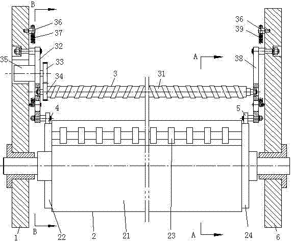
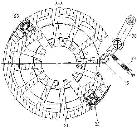
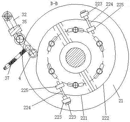
[0013] Refer to attached figure 1 , attached figure 2 , attached image 3 , a cam-controlled follower pressure roller of the present invention

[0014] Mechanism, which is composed of wallboard Ⅰ1, roller mechanism 2, pressure roller mechanism 3, rolling part Ⅰ4, rolling part Ⅱ5, wallboard Ⅱ6, the roller mechanism 2 is supported on the wallboard Ⅰ1 and wallboard Ⅱ6 through the supporting parts; the pressure roller mechanism 3 is set on the wallboard I1 and wallboard II6; the rolling element I4 and the rolling element II5 are arranged on the roller mechanism 3 through the shaft; the roller mechanism 3 is composed of the roller 31, the connecting plate I32, the gear I33, and the gear II34 , a motor 35, a connecting shaft 36, a compression spring assembly I37, a connecting plate II38, and a compression spring assembly II39. The pressure roller 31 is a rubber roller body with opposite helical directions in the left and right parts; the connecting plate I32, The connecting plat...


PUM


Abstract

The invention relates to a cam-controlled follow-up pressure roller mechanism for detecting the quality of printed matter in the printing industry. The supporting parts are supported on the wall board I and the wall board II; the pressure roller mechanism is set on the wall board I and the wall board II; the rolling parts I and II are set on the pressure roller mechanism through the shaft; Integrated cam, so as to ensure the synchronization of the positions of the two cams; because of the structure of the cam and the compression spring assembly, the relative position between the landing point of the pressure roller and the front edge of the paper can be precisely controlled; because the rotation speed of the pressure roller is controlled by the motor The rotation speed is matched to ensure the stability of the paper when it is flattened; because the pressure roller adopts the rubber roller body structure with two parts with opposite spiral directions on the left and right, it can fully expand the paper and ensure the accurate detection of the printed product by the laser detection head.

Description

technical field [0001] The invention relates to a sheet-fed inspection machine for inspecting the quality of printed matter in the printing industry, in particular to a cam-controlled follow-up roller mechanism. Background technique [0002] After retrieving relevant patent documents, a cam-controlled follow-up roller mechanism with the same structure as the present invention has not been found yet. Existing sheet-fed inspection machines generally use conveying rollers and conveyor belts to move the paper. Since the friction between the paper and the conveying rollers and conveyor belts is not easy to control, it is easy to cause the paper to move out of control, making the paper wrinkled and uneven. , affecting the detection performance. As the printing accuracy requirements of sheet-fed offset printing machines are getting higher and higher, some original structures can no longer meet the inspection requirements of high-precision printing products, so it is necessary to i...

Claims


Application Information

Patent Timeline
Patent Type & Authority Applications(China)
IPC IPC(8): B41F33/00G01N21/84G01N21/89
CPCB41F33/0036G01N21/84G01N21/89G01N21/8914G01N2021/845G01N2021/8917
Inventor 宗兵曹建平席宏兵周金华
Owner 江苏昌昇集团股份有限公司
Learn More