
Remote controller with floating waterproof function

A technology of remote control and function, applied in the field of remote control, can solve the problem of not enough to float the remote control from the water, make the remote control sink into the water at once, cannot find the position of the remote control at the first time, and do not know The remote control is accidentally dropped into the water, etc., to achieve the effect of good waterproof effect, simple structure and good waterproof effect

Active Publication Date: 2017-12-08
FOSHAN HUIKAIDA TECH CO LTD
View PDF9 Cites 1 Cited by
  • Summary
  • Abstract
  • Description
  • Claims
  • Application Information

AI Technical Summary

Problems solved by technology

In order to facilitate the use of remote controllers in humid environments such as kitchens or bathrooms, more and more remote controllers are now designed with waterproof structures, and the remote controller is a control device that users can place anywhere. If the remote control falls into a container containing water such as a bathtub or a wash basin, although a sealed cavity is formed in the remote control with a waterproof design, the sealed cavity is used to install circuit boards and other components, and the stored air Less, it is not enough to float the remote control from the water, so that the remote control will sink into the water at once, so that the user can not only find the position of the remote control at the first time, but even do not know that the remote control accidentally fell into the water. In addition, when the user picks up the remote controller, he needs to put his hand into the water to find and salvage the remote controller, which brings inconvenience to the user. Therefore, it is urgent to improve the existing remote controller.

Method used


Image

  • Remote controller with floating waterproof function
  • Remote controller with floating waterproof function
  • Remote controller with floating waterproof function

Examples


Embodiment Construction

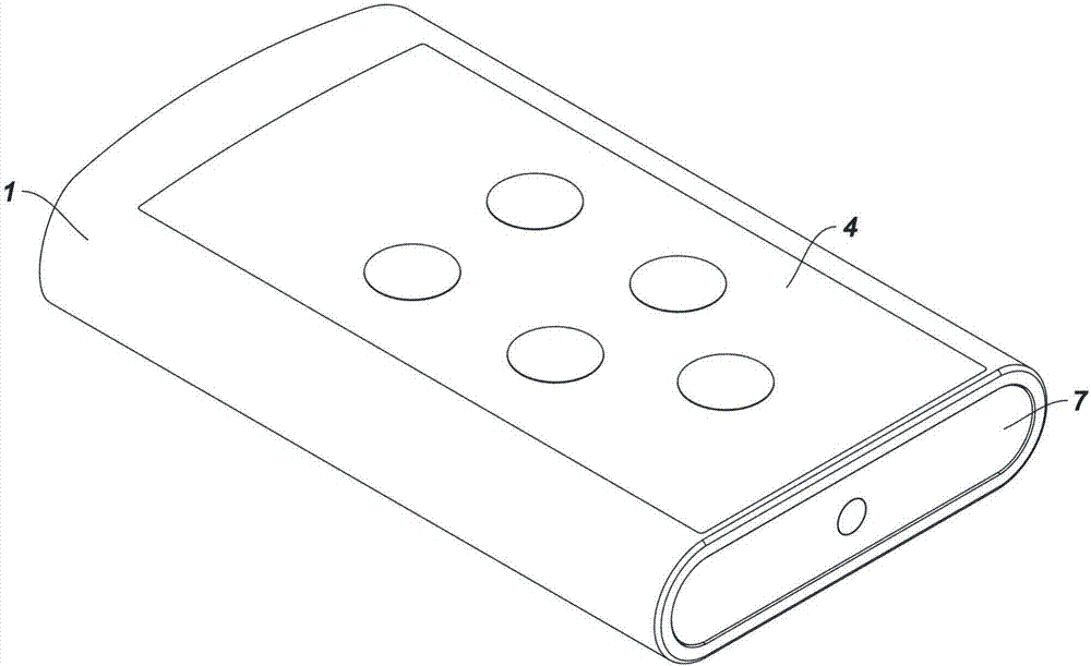
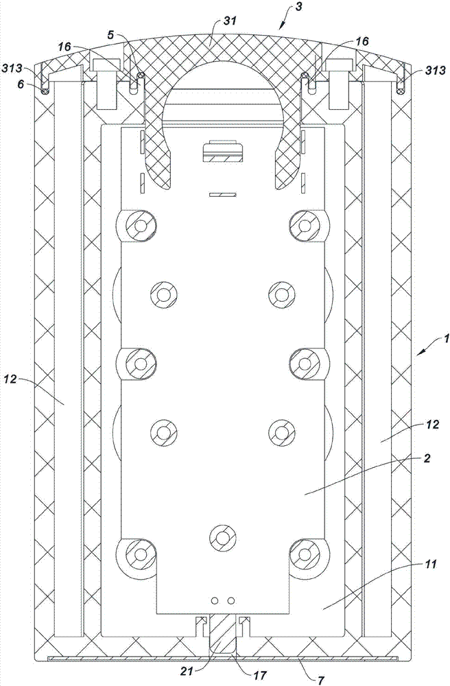
[0023] Such as figure 1 , figure 2 , image 3 , Figure 4 , Figure 5 , Figure 6 , Figure 7 , Figure 8 , Figure 9 As shown, a remote control with a floating and waterproof function described in the present invention includes a main housing 1, a main board 2, a battery assembly 3, and a panel assembly 4. The main housing 1 is made of plastic, and the main housing 1 An installation cavity groove 11 is provided on the top surface of the main housing, an air cavity groove 12 is respectively provided on both sides of the installation cavity groove 11, and an embedded groove 13 is arranged on the rear end surface of the main shell 1, and the embedded groove 13 is compatible with the installation Through holes 14 are also provided between the cavity grooves 11, and the cavity notches of the air cavity grooves 12 are set on the groove bottoms of the embedded grooves 13 respectively; the main board 2 is installed in the installation cavity groove 11; the panel The componen...


PUM


Abstract

The invention relates to a remote controller with a floating waterproof function. The remote controller comprises a main housing, a main board, a battery assembly and a panel assembly. The main housing is made of plastic. A mounting cavity groove is arranged on the top surface of the main housing. The two sides of the mounting cavity groove are provided with air cavity grooves. An embedding groove is arranged on the rear end surface of the main housing. A through hole is also arranged between the embedding groove and the mounting cavity groove. The notch of each air cavity groove is disposed on the embedding groove. The main board is installed in the mounting cavity groove. The panel assembly covers the mounting cavity groove and is in sealed connection with the main housing. The battery assembly comprises a battery holder and a battery mounted on the battery holder. The battery holder is installed in the embedding groove. A sealing structure is arranged between the battery holder and the embedding groove. The battery holder cooperates with each air cavity groove to form two air cavities. The battery penetrates through the through hole to enter the mounting cavity groove and to be connected with the main board. The remote controller is simple in structure, reasonable in design, floatable on the water surface, and convenient to use.

Description

technical field [0001] The invention relates to the technical field of remote controllers, in particular to a remote controller with a floating waterproof function. Background technique [0002] With the advancement of science and technology, the popularity of household appliances and the continuous improvement of functions, remote controls have become an indispensable tool in people's daily life. In order to facilitate the use of remote controllers in humid environments such as kitchens or bathrooms, more and more remote controllers are now designed with waterproof structures, and the remote controller is a control device that users can place anywhere. If the remote control falls into a container containing water such as a bathtub or a wash basin, although a sealed cavity is formed in the remote control with a waterproof design, the sealed cavity is used to install circuit boards and other components, and the stored air Less, it is not enough to float the remote control fr...

Claims


Application Information

Patent Timeline
Patent Type & Authority Applications(China)
IPC IPC(8): H05K5/06H01H9/02
CPCH05K5/061H01H9/0242Y02E60/10
Inventor 冯炽强罗国强
Owner FOSHAN HUIKAIDA TECH CO LTD
Learn More