Video monitoring system and video recording control method thereof

A video surveillance system and surveillance camera technology, applied in CCTV systems, components of TV systems, TVs, etc., can solve the problems of loss of sensitivity, wasting precious time and storage space, and spending a lot of time viewing videos, etc. Effects that increase productivity, reduce redundant video recording, save storage space and time required for viewing

Inactive Publication Date: 2017-12-08
重庆万建电子工程有限责任公司
View PDF5 Cites 1 Cited by
  • Summary
  • Abstract
  • Description
  • Claims
  • Application Information

AI Technical Summary

Problems solved by technology

[0002] In the existing video surveillance system, when viewing the surveillance video in the later stage, due to too much redundant information, there is very little key information that can be really used, and it often takes a lot of time to view the video, which wastes a lot of valuable information on the one hand. Time and storage space. On the other hand, people are prone to fatigue after watching videos for a long time, which leads to a decrease in concentration, and loses sensitivity when important information appears. It is easy to miss information and cause irreparable losses.

Method used


Image

  • Video monitoring system and video recording control method thereof

Examples


Embodiment 1

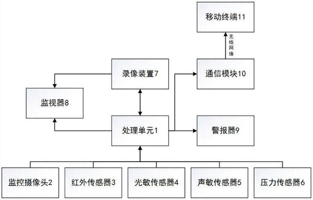
[0022] A video monitoring system, which is set at the entrance and exit to be monitored, such as figure 1 As shown, it includes a control unit 1, a monitoring camera 2, an infrared sensor 3, a photosensitive sensor 4, an acoustic sensor 5, a pressure sensor 6, a video recording device 7, and a monitor 8. The monitoring camera 2, an infrared sensor 3, and a photosensitive sensor 4 , the acoustic sensor 5 is arranged on the side or top of the entrance and exit, and the pressure sensor 6 is arranged on the floor of the entrance and exit; 6. The video recording device 7 is connected; the control unit also includes a clock module. The control unit can adopt MCU or PLC. On the one hand, the monitor can be used for on-site monitoring, and can also transfer the video files in the video recording device to the monitor for viewing afterwards.

[0023] This system can carry out very strict monitoring at the entrance and exit to be monitored.

[0024] As an optimized solution, an alarm...

Embodiment 2

[0026] A video surveillance system recording control method, adopting the video surveillance system of any one of the schemes in embodiment 1, its steps are as follows:

[0027] S1: The control unit issues instructions to turn on the monitoring camera, infrared sensor, photosensitive sensor, sound sensitive sensor, pressure sensor and monitor;

[0028] S2: When the infrared sensor, photosensitive sensor, sound sensitive sensor, and pressure sensor receive abnormal signals, the abnormal information is sent to the control unit independently (the abnormal signal is when the infrared sensor detects a change in the temperature of the target position, the photosensitive sensor detects Changes in light and shade, sound sensors detect changes in the intensity of surrounding sound waves, and pressure sensors detect changes in the pressure on the floor that reach the set threshold);

[0029] S3: When the control unit receives abnormal signals sent from at least two sensors in the infrar...


PUM


Abstract

The invention discloses a video monitoring system comprising a control unit, a monitoring camera, an infrared sensor, a photosensitive sensor, a sound-sensitive sensor, a pressure sensor, a video recording device and a monitor. The monitoring camera, the infrared sensor, the photosensitive sensor and the sound-sensitive sensor are arranged on the side surface or the top part of the access port. The pressure sensor is arranged on the floor of the access port. The control unit is connected with the monitoring camera, the infrared sensor, the photosensitive sensor, the sound-sensitive sensor, the pressure sensor and the video recording device. The control unit also comprises a clock module. The invention also discloses a video recording control method of the video monitoring system. Trigger type video recording of video monitoring can be realized by using multiple induction devices so that recording of redundant videos can be greatly reduced on the basis of reserving important information, the storage space and the required viewing time can be saved and the work efficiency can be greatly enhanced.

Description

technical field [0001] The invention belongs to the field of video monitoring, and in particular relates to a video monitoring system and a video recording control method. Background technique [0002] In the existing video surveillance system, when viewing the surveillance video in the later stage, due to too much redundant information, there is very little key information that can be really used, and it often takes a lot of time to view the video, which wastes a lot of precious time on the one hand. Time and storage space. On the other hand, people are prone to fatigue after watching videos for a long time, which leads to a decrease in concentration. Instead, they lose sensitivity when important information appears, and it is easy to miss information, causing irreparable losses. Contents of the invention [0003] Aiming at the deficiencies in the prior art, the present invention provides a video surveillance system capable of retaining useful information, saving storage ...

Claims


Application Information

Patent Timeline
Patent Type & Authority Applications(China)
IPC IPC(8): H04N7/18H04N5/76G01D21/02
CPCH04N7/18G01D21/02H04N5/76
Inventor 岳军刘春莲汪洋徐守中
Owner 重庆万建电子工程有限责任公司
Why Eureka
Try Eureka