
PE flame-retardant electric power sheath tube

A sheathed tube and electric power technology, which is applied in the direction of power cables, circuits, and insulated cables with shielding layers/conductive layers, can solve problems such as lack of flame retardancy, property loss, and serious fires, and prevent the spread of fire , to avoid corrosion, to avoid the effect of electric shock accidents

Inactive Publication Date: 2017-12-08
RONGCHENG PIPE IND
View PDF0 Cites 3 Cited by
  • Summary
  • Abstract
  • Description
  • Claims
  • Application Information

AI Technical Summary

Problems solved by technology

[0002] With the frequent occurrence of fire accidents, people's awareness of the fire hazard of wires and cables is deepening, and the relevant departments have higher and higher requirements for the performance of fire resistance and flame retardancy of wires and cables. Hazards, long recovery time and other characteristics will bring huge losses to the national economy and the lives and property of the people, the overall design is not reasonable enough, and the practicability is poor
[0003] The power sheath tubes in the prior art generally use metal tubes or plastic tubes, but the disadvantages of these two materials are also very obvious. Metal tubes do not have high temperature resistance, and metal tubes are conductive. Electric shock accidents are very likely to occur in the case of a fire, and the plastic pipe does not have the effect of flame retardancy. In the event of a fire, it is easy to burn itself. would result in greater property damage

Method used

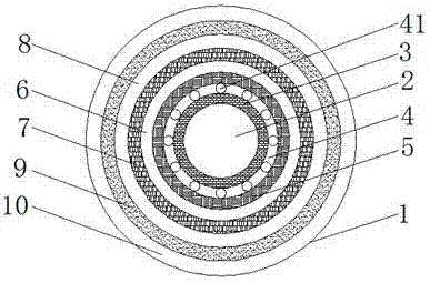
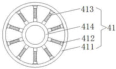
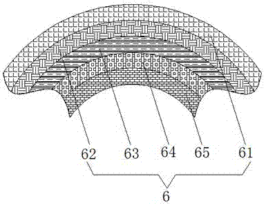

Image

  • PE flame-retardant electric power sheath tube
  • PE flame-retardant electric power sheath tube
  • PE flame-retardant electric power sheath tube

Examples


Embodiment Construction

[0015] The following will clearly and completely describe the technical solutions in the embodiments of the present invention with reference to the accompanying drawings in the embodiments of the present invention. Obviously, the described embodiments are only some, not all, embodiments of the present invention. Based on the embodiments of the present invention, all other embodiments obtained by persons of ordinary skill in the art without making creative efforts belong to the protection scope of the present invention.

[0016] see Figure 1-3 , the present invention provides a technical solution: a PE flame-retardant electric power sheath tube, including a sheath tube body 1, the cross-sectional area of ​​the sheath tube body 1 is a circular structure, and the inner center of the sheath tube body 1 is provided with Circular hollow groove 2, the outside of circular hollow groove 2 is tightly wrapped with a layer of insulating layer 3, through the design of insulating layer 3, ...


PUM


Abstract

The invention discloses a PE flame-retardant electric power sheath tube. The PE flame-retardant electric power sheath tube comprises a sheath tube body, wherein the cross sectional area of the sheath tube body is of a circular structure; a circular hollow groove is formed in the center of the interior of the sheath tube body; the exterior of the circular hollow groove tightly packages an insulating layer; the exterior of the insulating layer tightly packages a shockproof layer; the interior of the shockproof layer is provided with a shockproof ball; the shockproof ball comprises an outer ring, a damping rod, a damping spring and an inner ring, the inner ring is arranged on the inner side of the outer ring, and the damping rod is arranged between the outer ring and the inner ring. According to the PE flame-retardant electric power sheath tube, the design of the insulating layer plays an insulation role, the occurrence of an electric shock accident due to electric leakage of an electric wire is avoided, the design of a thermal insulation and flame retardance layer can play a flame retardance role under the condition of a fire disaster, so that the situation that the fire burns more and more furiously is avoided, the spreading of the fire is blocked, and the internal electric wire is also protected from being damaged.

Description

technical field [0001] The invention relates to the technical field of power protection, in particular to a PE flame-retardant power sheath tube. Background technique [0002] With the frequent occurrence of fire accidents, people's awareness of the fire hazard of wires and cables is deepening, and the relevant departments have higher and higher requirements for the performance of fire resistance and flame retardancy of wires and cables. Hazards, long recovery time and other characteristics will bring huge losses to the national economy and the lives and properties of the people. The overall design is not reasonable enough and the practicability is poor. [0003] The power sheath tubes in the prior art generally use metal tubes or plastic tubes, but the disadvantages of these two materials are also very obvious. Metal tubes do not have high temperature resistance, and metal tubes are conductive. Electric shock accidents are very likely to occur in the case of a fire, and th...

Claims


Application Information

Patent Timeline
Patent Type & Authority Applications(China)
IPC IPC(8): H01B7/17H01B7/18H01B7/28H01B7/29H01B7/295H01B9/02
CPCY02A30/14H01B7/295H01B7/17H01B7/1875H01B7/28H01B7/29H01B9/02
Inventor 朱加荣虞敏
Owner RONGCHENG PIPE IND
Learn More