
Preheating furnace with uniform preheating function

A preheating furnace, uniform technology, applied in the direction of preheating costs, furnaces, furnace components, etc., can solve the problems of uneven preheating of workpieces, high operating intensity, uneven temperature, etc., to achieve good preheating effect, uniform temperature, The effect of reducing energy consumption

Active Publication Date: 2017-12-01
NINGBO HUAXING SCI & TECH
View PDF7 Cites 1 Cited by
  • Summary
  • Abstract
  • Description
  • Claims
  • Application Information

AI Technical Summary

Problems solved by technology

[0002] At present, most of the equipment used for component preheating in large and medium-sized chemical fiber industries are well-type preheating furnaces, box-type preheating furnaces, and small horizontal preheating furnaces, which generally have uneven temperature, high operating strength, and poor sealing performance. , high energy consumption, and small scope of application. For components with high preheating requirements or large batches and large volumes, the use effect is poor. At the same time, the existing preheating furnace does not preheat the workpiece uniformly.

Method used


Image

  • Preheating furnace with uniform preheating function
  • Preheating furnace with uniform preheating function
  • Preheating furnace with uniform preheating function

Examples


Embodiment Construction

[0027] The present invention will be further described below in conjunction with the embodiments and with reference to the accompanying drawings. It should be understood that the following specific embodiments are only used to illustrate the present invention and are not intended to limit the scope of the present invention. It should be noted that the words "front", "rear", "left", "right", "upper" and "lower" used in the following description refer to the direction in the figure, and the words "inner" and "outer ” refer to directions towards or away from the geometric center of a particular part, respectively.

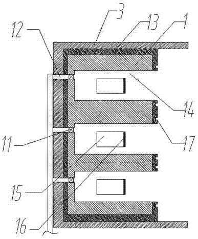
[0028] Such as figure 1 Shown is a preheating furnace with uniform preheating, including a door panel 5, a preheating furnace body 1, and a heat supply box 2 for supplying heat to the preheating furnace body. A plurality of preheating chambers 14 are arranged in the preheating furnace body, and air inlets 19 are arranged on the left and right side walls of each prehe...


PUM


Abstract

The invention discloses a preheating furnace with an uniform preheating function. The preheating furnace comprises a shell, a door plank, a preheating furnace body and a heating box. Multiple preheating cavities are formed in the preheating furnace body. A drawer type containing box is arranged in each preheating cavity. Containing box protruding blocks are correspondingly arranged on the left end side face and the right end side face of each containing box body. Wind shields are correspondingly arranged on air inlets in the left side wall and the right side wall of each preheating cavity. The rear ends of the wind shields are connected with springs. The upper ends and the lower ends of the wind shields are embedded into guide grooves in the upper inner walls and the lower inner walls of the air inlets. A valve plate protruding block is arranged on the inner side face of each wind shield. Through the wind shields arranged on the side walls of the preheating cavities, through the cooperation of the protruding blocks on the drawer type containing boxes and the protruding blocks on the wind shields, the wind shields can be opened when the drawer type containing boxes are inserted into the preheating box bodies, and hot air is introduced; and when the drawer type containing boxes are pulled out, the wind shields return to the original positions, and the ventilation is closed, so that the excessive heating can be avoided, the energy consumption is lowered, and the energy is saved.

Description

technical field [0001] The invention relates to the field of preheating furnaces, in particular to a preheating furnace with uniform preheating. Background technique [0002] At present, most of the equipment used for component preheating in large and medium-sized chemical fiber industries are well-type preheating furnaces, box-type preheating furnaces, and small horizontal preheating furnaces, which generally have uneven temperature, high operating strength, and poor sealing performance. , high energy consumption, and small application range. For components with high preheating requirements or large batches and large volumes, the use effect is poor. At the same time, the existing preheating furnace does not preheat the workpiece uniformly. Contents of the invention [0003] The object of the present invention is to provide a preheating furnace with uniform preheating in order to overcome the above problems. [0004] In order to achieve the above object, the method adopte...

Claims


Application Information

Patent Timeline
Patent Type & Authority Applications(China)
IPC IPC(8): F27D13/00
CPCF27D13/00
Inventor 胡全林
Owner NINGBO HUAXING SCI & TECH
Learn More