
Movable formwork system and construction method thereof

A mobile formwork and system technology, applied in artificial islands, earthwork drilling, water conservancy projects, etc., can solve problems affecting construction progress, complicated disassembly, labor-intensive, etc., to reduce labor costs, solve the trouble of disassembly and installation, and reduce labor The effect of loss

Active Publication Date: 2017-12-01
福建建中建设科技有限责任公司
View PDF5 Cites 5 Cited by
  • Summary
  • Abstract
  • Description
  • Claims
  • Application Information

AI Technical Summary

Problems solved by technology

During the construction process of the overall channel type culvert formwork, it is still very complicated to disassemble after installation. Underground pipe galleries, culverts and tunnels are generally constructed in sections, and repeated installations are required during the gradual completion process, which consumes labor and affects the overall construction. Construction Schedule

Method used


Image

  • Movable formwork system and construction method thereof
  • Movable formwork system and construction method thereof
  • Movable formwork system and construction method thereof

Examples


Embodiment Construction

[0038] The present invention will be described in detail below in conjunction with the accompanying drawings and specific embodiments.

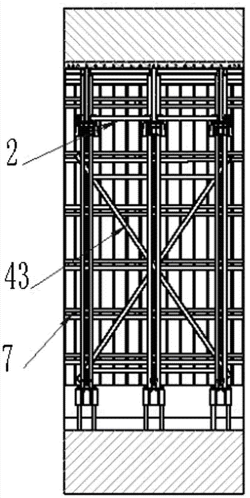
[0039] see Figure 1-5 , a mobile formwork system, including a "Π"-shaped aluminum formwork support plate 1, horizontally arranged transverse truss beams 2, several top support members 3, two vertically arranged vertical truss columns 4, and horizontal support members 5 and a number of vertical supports 6; chamfers are provided at the corners of the aluminum formwork support plate 1; the transverse truss beam 2 abuts against the inner roof of the aluminum formwork support plate 1, and the side walls of the two vertical truss columns 4 respectively abut against On the two inner side walls of the aluminum formwork support plate 1, the upper ends of the two vertical truss columns 4 are respectively fixedly provided with sliding sleeves 41 parallel to the transverse truss beam 2 and having a side surface of "凵" shape, and the lower parts of the t...


PUM


Abstract

The invention relates to a movable formwork system and a construction method thereof. The movable formwork system comprises an II-shaped aluminum mold supporting plate, a horizontally-arranged transverse truss girder, a plurality of top contraction and expansion parts, two vertically-arranged vertical truss columns, a horizontal supporting parts and a plurality of vertical supporting parts. Chamfers are arranged at bevels of the aluminum mold supporting plate. The transverse truss girder abuts against an inner top plate of the aluminum mold supporting plate. The side walls of the two vertical truss columns abut against the two inner side walls of the aluminum mold supporting plate. Sliding sleeving parts which are parallel to the transverse truss girder are fixedly arranged at the upper ends of the two vertical truss columns, and the side faces of the sliding sleeving parts are in a U shape. Rod parts of the lower portions of the two ends of the transverse truss girder are sleeved with the sliding sleeving parts of the two vertical truss columns correspondingly. The sliding sleeving parts can slide along the rod parts of the lower portion of the transverse truss girder. One end of each top contraction and expansion part is fixedly connected with the lower portion of the transverse truss girder, and the other end of each top contraction and expansion part is fixedly connected with the adjacent vertical truss column. The vertical truss columns on the two sides are enabled to draw together to the middle or stretch to the two sides through hydraulic contracting or stretching of the top contraction and expansion parts.

Description

technical field [0001] The invention relates to a mobile formwork system and a construction method thereof, which is suitable for the initial lining construction stages of underground pipe galleries, culverts and tunnels, and belongs to the field of construction engineering. Background technique [0002] For the construction of the culvert roof by the traditional scaffolding method, a bowl-shaped scaffolding bracket or ordinary Φ48 steel pipes are used to build a full house scaffolding with corner fasteners. The internal rod system consists of vertical rods (according to a certain longitudinal distance and horizontal distance), horizontal rods (according to a certain step distance), scissors braces (set up according to a certain angle and distance, and the scissors braces with large volumes are also divided into horizontal scissors braces, Longitudinal scissors bracing, horizontal scissors bracing) support system, jointly support the jacking, main keel (square wooden beam), ...

Claims


Application Information

Patent Timeline
Patent Type & Authority Applications(China)
IPC IPC(8): E02D29/045E01F5/00E21D11/10
CPCE21D11/102E01F5/005E02D29/10Y02E10/20
Inventor 李洪强何文林洪启增蔡宁建米国栋
Owner 福建建中建设科技有限责任公司
Learn More