
Shear anchor structure and its construction method

A technology of anchoring structure and anchoring section, which is applied in the direction of basic structure engineering, excavation, construction, etc., can solve the problems of small shear deformation, low shear resistance of anchoring structure, too conservative anchoring structure, etc., and achieve the effect of not being easily damaged

Active Publication Date: 2020-02-07
四川钦耀炜岳建设工程有限公司
View PDF4 Cites 0 Cited by
  • Summary
  • Abstract
  • Description
  • Claims
  • Application Information

AI Technical Summary

Problems solved by technology

[0005] This method of pre-reinforcement of the anchorage structure that does not allow deformation of the slope rock mass may have two problems: one is that the actually designed anchorage structure is too conservative
The exertion of the shear strength of the rock layer is beneficial to the stability of the slope, but the exertion of the shear strength requires the relative displacement trend or even relative displacement of the rock mass on both sides of the rock layer. Deformation without considering the shear strength of the rock layer will inevitably lead to the actual design of the anchorage structure is too conservative
Second, there is a risk that the anchoring structure will lose its anchoring capacity due to shear damage
When the slope deforms along the direction of the slope, the preset anchorage structure will inevitably undergo shear deformation. Because the shear resistance of the anchorage structure is very low and the allowable shear deformation is very small, the anchorage structure is prone to shear deformation or The shear stress is too large and damaged, thus losing the anchoring ability

Method used


Image

  • Shear anchor structure and its construction method
  • Shear anchor structure and its construction method
  • Shear anchor structure and its construction method

Examples


Embodiment Construction

[0035] The present invention will be further described below in conjunction with the accompanying drawings and specific embodiments, so that those skilled in the art can better understand the present invention and implement it, but the examples given are not intended to limit the present invention.

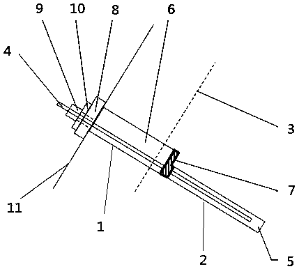
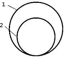
[0036] Such as figure 1 Shown is a schematic structural view of an embodiment of the shear-type anchoring structure of the present invention. The scissor-type anchoring structure of this embodiment includes a free section borehole 1 , and an anchor section borehole 2 is provided on the inner bottom surface of the free section borehole 1 . The borehole 1 in the free section extends inward to the inside of the potential slip surface 3 of the slope body 11, and the boreholes 2 in the anchor section are all located in the stable rock mass inside the potential slip surface 3 of the slope body, and the borehole 1 in the free section and the anchor section An anchor bar 4 is arranged in...


PUM


Abstract

The invention discloses a shear-stress-reduction anchoring structure. The shear-stress-reduction anchoring structure comprises a free section drill hole. The inner bottom surface of the free section drill hole is provided with an anchoring section drill hole. The free section drill hole extends inwards to the inner side of a potential slip plane of a slope. An anchor bar is arranged in the free section drill hole and the anchoring section drill hole. The outer end of the anchor bar extends out of the free section drill hole. The anchoring section drill hole is filled with mortar wrapped outside the anchor bar. The free section drill hole is filled with a low-compression-modulus grouting material wrapped outside the anchor bar. An anchorage device which is arranged on the anchor bar in a sleeving mode and used for tensioning and fixing the anchor bar is arranged at an orifice on the outer side of the free section drill hole. The invention further discloses a construction method of the shear-stress-reduction anchoring structure. According to the shear-stress-reduction anchoring structure and the construction method thereof, the technical purpose of stabilizing the slope is achieved by means of the shearing strength between layers of rock stratums.

Description

technical field [0001] The invention belongs to the technical field of geotechnical engineering slope reinforcement, in particular to a shear-type anchorage structure and a construction method thereof. Background technique [0002] A bedding rock slope refers to a rock slope in which the inclination of the rock layer is consistent or basically consistent with the orientation of the slope surface, and it is a common and easily unstable rock slope type. When performing slope cutting and excavation on bedding rock slopes, because the rock layer is usually a weak surface, if the inclination angle of the rock layer and the slope angle of the slope meet certain conditions, the slope rock mass is easy to collapse under the action of gravity. Integral or local instability and failure along the rock formation may cause losses or disasters. [0003] In order to avoid the instability and failure of bedding rock slope, it is very necessary to take reasonable support and reinforcement m...

Claims


Application Information

Patent Timeline
Patent Type & Authority Patents(China)
IPC IPC(8): E02D5/74E02D15/04E02D17/20
CPCE02D5/74E02D15/04E02D17/20E02D2250/003E02D2300/0021E02D2600/20
Inventor 王俊杰刘云飞张慧萍赵迪杨洋贺林林
Owner 四川钦耀炜岳建设工程有限公司
Learn More